Two thoughts on clamping:
- ?Conventional band clamp going all the way around:

I have a both.? The latter ones aren't cheap, but they work great
when you need to apply something in place.
On 7/15/2024 1:53 PM, David
Luckensmeyer via groups.io wrote:
Hi Brian:
?
Apologies, I
should have provided more detailed photos.
?
The bookcase
uprights in Zebrano are composed of a solid wood core
lamination with 3mm thick shop sawn Zebrano veneers on both
faces. This is the material I’ve been machining for the half
laps.
?

?

?
If you look
closely at the photo below, you can see that I have edge
laminated the back side of the uprights with Zebrano
veneers, prior to the half lap machining process. This
worked well.
?

?
The problem
with the front edge is that it will be curved. I could not
machine the curve until the half lap joints were done. This
means that the front edge laminations have to be applied
after the machining is done.
?
The
horizontal shelves sit out from the uprights by 20mm. In the
photo below you can see how the shelves are proud, and you
can see the laminated nature of the uprights.
?

?
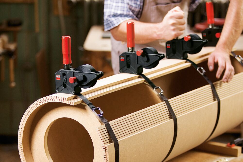
My dilemma
is how best to apply/trim laminations to the front edge,
between each shelf, on the soon-to-be-curved front
edges of the uprights. Gluing will be tedious. I’m thinking
of using dozens of clamps like this:
?

?
But how to
trim the laminations to length after the glue dries? I guess
the flush cut hand saw method is the best one I can think
of.
?
Lucky
?
I'm
not following the need to laminate the front edges
of the uprights? The sides are solid wood,
correct? Are you doing it to cover the slots and
make the front surface proud of the shelves by
2mm? Color me confused...
On Sunday,
July 14, 2024 at 08:25:22 PM MST, David
Luckensmeyer <dhluckens@...> wrote:
Hi
FOG:
?
By
way of update, the aforementioned Leitz
blade is phenomenal. It cuts as smoothly as
any blade I’ve owned which is saying
something for such a large blade with
relatively narrow kerf width of 3.5mm. The
details appear again here, just in case
anyone else wants to consider it as a 400mm
blade option: item number 133130, 400mm
diameter, 3.5mm kerf. 2.5mm body, 30mm bore,
96 teeth, 10 degree irregular pitch, ATB.
?
This
is the first time I’ve used a blade of this
size. The dust it throws off is horrendous;
I assume it has something to do with making
125mm and 135mm deep cuts. My 3M Dustmaster
is in continuous use.
?

?
This
is very fine dust from a couple of hours
work at the saw:

?
In
the end, the powered rip fence and
associated programming has been gold. I’ve
used the special programs on the overhead
display a lot, including rebating,
trenching, etc., but I must say that I have
not really used the specific programming
mode for the Kappa 400. It is wonderful.
?
There
are 10 program positions, and each of those
10 has 100 spaces to enter specific
parameters that can be called up at the
press of an arrow key and the start button
on the overhead display. You can imagine its
use as follows. For the first half lap
joint, I needed a cut at 125mm deep, at
120mm from the end of the Zebrano board. So
for P1 (where “P” stands for “Program”),
number 1, I’ve entered 125mm blade height, 0
degrees blade tilt, and 120mm rip fence
position. It works out that I need the fence
(which is acting as a bump stop) to move
over 16.1mm to give the half lap width I
need, so I’ve programmed the number 2
position with 125mm blade height, 0 degrees
blade tilt, and 136.1mm rip fence position
for the second cut (i.e. both shoulders of
the lap joint). And so forth and so on for
all 7 half lap joint positions along the
bookcase upright. After 4 cuts, my rip fence
is out at about 1150mm. So at this point I
have to flip the upright end for end and
start again on the final 3 shelf positions
(working from the top of the uprights). This
is made easy using the programming on the
Kappa 400. Obviously my uprights all need to
be dimensioned accurately which I have done.
?
I
forgot to say that I could not use special
programming function which the Kappa 400
offers, where the rip fence can be
programmed for a number of grooves or
trenches of a specific width and depth, at
fixed intervals. The reason? Because my
shelves are deeper at the bottom and much
shallower at the top, so the position of
each half lap joint on the uprights is of
decreasing distance (from the bottom up) and
increasing distance (from the top down).
Programming mode made this process easy.
Seems like cheating. Comparing uprights at
random, and I’d say the 0.1mm claimed
tolerance is verified. I’ve used lots of
compressed air between cuts to make sure
registrations are accurate, and I’d say the
Kappa 400 has worked as advertised. I
strongly recommend a Felder powered rip
fence as a wonderful option.
?
Anyway,
the 3.5mm blade width allowed for 6 passes
to remove the waste for each half-lap joint.
No drilling, no knocking out timber, no
marking lines, and definitely no chiselling.
I’ve decided I can live with the bumpy but
regularly reliable surface in the middle of
each half lap joint.
?


?
Last
night I assembled the first and smallest of
the bookcases. It went together very nicely
but I think I’m going to tweak the Walnut
shelves (through the wide belt sander) so
the fit is less tight. In the picture below,
you’ll see the upper shelves don’t seem the
correct width. That’s because the uprights
have not been curved yet, to reflect the
design where shelves at the bottom are full
depth (260mm) while the shelves become less
deep by the top (210mm).
?
l’ll
use a template to pattern route the curve
after I’m completely satisfied with the
joinery. And then another tricky part is
headed my way: I have to edge laminate 2mm
solid Zebrano onto the front edges of all
the curved uprights. I’ve agonised over this
because I could not cut the curves and
laminate before machining the joints because
I needed parallel edges. Adding the solid
wood lamination to the edge after the
machining is going to be time consuming and
I’m not sure how best to do it. I could
apply over long sections to each curved edge
(between shelves) and then flush them, but
how?
?
-
Router
(risk of splinters)
-
Chisel
(not looking forward to that)
-
Flush
cut hand saw (might be the best option)
-
Cut the
lamination exactly to length and glue it
exactly in position…
?
If
I used the flush cut handsaw, I could use
overlength Zebrano pieces (but maintaining
continuous grain) and then not stress the
clamping process. I guess after that many
cuts (224 to be precise) I’ll be pretty good
with the flush cut saw? Thanks for your
brainstorming thoughts!
?

?
?
Lucky
?
Hi
David B and Michael:
?
Funny
you should mention the flatbed CNC.
Although not the same, I have been
pondering how much use I’d get out of
a Shaper Origin. That tool would fit
nicely somewhere in my shop!
?
Thanks
David for your vote on the vertical
method. I think the clean corners are
swaying me strongly for that option.
I’ve wondered if I make a very
accurate registration jig and use a
small pattern bit (I can get an 8mm
dia. bit from across town) to
establish the majority of the 20mm
flat across the joint, then there
would be very little chisel work at
all:
?
·????????
corners
squared by the saw blade
·????????
majority
of waste drilled out
·????????
shoulder
established by the pattern bit
·????????
minor
chisel work to finish.
?
Your
jig making has always been a source of
inspiration for me. Your lock mitre
jig is especially egregious! I
absolutely love it. Of course, now I
know I should have made a much larger
vertical jig that does not depend on
the crosscut fence for registration.
Something like what you’ve done would
have been much better. Cheers.
?
Lucky
?
I actually
like your original concept of
using the rip as a bump-stop, a
400mm blade cutting both edges,
and a jig on the crosscut fence to
hold the material vertically.
?Here’s a couple more jig I’ve
made to stimulate your thinking.
?I could quibble over the actual
jig configuration (hence these
photos of jigs I’ve made to hold
vertical materials on the slider
as food for thought).
This is for
cutting lock miter joints:?
 ?? ??
This one is
for finger joints - which is a
shallower type of thing you are
doing:


?
?
On Jul 9,
2024, at 3:18?PM, David
Luckensmeyer via groups.io
<dhluckens@...> wrote:
?
Oh
wow! The video came
through. I love it. No
one would even think
the drawer is there!
Thanks for sharing.
?
Lucky
?
Lucky, as I
further
thought about
my suggestion
I realized it
was lunacy. I
think you are
correct about
returning to
the horizontal
setup. I know
we are talking
about a lot of
work for 280
repititions!?
I had a few do
overs and
re-designs as
I progressed
but ultimately
was very happy
with the
result.?
To
answer?your
question, it
is a drawer
that holds
DVD’s on the
bottom level,
and Blu-rays
on the top
level as they
are both
different size
cases. The
drawer was
incorporated
into a raised
panel
staircase I
built 30 years
earlier and
had always
planned to
make a drawer
similar.
There is
hopefully an
attached video
below showing
final
install??
The CMT was
excellent;
best dado I
ever had but I
ran it on a
cabinet saw,
not on my
K700S. I used
a simple “box
joint jig”
that we all
learned in
woodworking
101 but made a
mistake
thinking I
could do the
sides
separately and
still have
things line
up. A couple
of tries
changing
methodology
were
necessary. The
drawer empty
without the
drawer front
was over 75
lbs made of
Maple. I used
Blum slides
(Blumotion)
with ?“Tip-on”
added for push
to open tech
to eliminate
visible
exterior
hardware.
?
On Tue, Jul
9, 2024 at
5:41?PM David
Luckensmeyer
via
<dhluckens=[email protected]> wrote:
Imran:
?
Thanks
for your
ideas. You’re
correct about
the slotting
blade. If I go
the vertical
machining
route I’ll
need nearly
every bit of
the 400mm
blade’s depth
of cut. If I
were to go
back to the
horizontal
setup, I could
remount the
dado blade,
set it to
maximum
height, and
make a partial
cut. This may
well be a
better
solution
because it
gives me the
exact width
(to match the
existing
shallower
trenches).
?
You
have rightly
identified the
time-wasting
point of
needing to
take two
passes
(minimum) and
then deal with
the waste by
drilling a
hole with a
forstner bit
to get rid of
the septum. I
would then
have to mark
and chisel the
waste which is
fine for 1-10
joints, but
not 280
trenches…
?
Brian:
?
That
looks awesome
what you’ve
made. Is it a
drawer insert
for plates?
I’m very
curious what
you thought of
the new CMT
dado stack?
What did you
like? What
didn’t you
like? Thanks
for sharing.
I’d rather not
run two 400mm
blades on the
slider. So
much to go
wrong! EEK.
?
Joe:
?
Love
those jigs.
Pictures speak
volumes. So
many ideas to
learn from.
Thank you.
?
Methodology
Quiz
How
would you make
280
non-through
cuts that have
to be
precisely
machined at
125mm deep and
20mm wide?
?
-
Vertical
method as
discussed to
date using the
400mm
sawblade, to
make two cuts
to establish
each shoulder,
drilling out
the waste, and
then A) mark a
line and use a
chisel to
square up the
joint, or B)
use a router
and small
pattern bit to
establish the
shoulder and
then chisel
out the
corners.
?
-
Horizontal
method using
the same dado
stack that
machined the
shallow
trenches, dado
raised all the
way up for the
stopped cut,
and then
employ either
option A or B
above to clean
up the joint.
?
-
Rely on
the existing
shoulders of
the trenches
(5mm deep on
both sides),
and use a
router and
pattern bit to
obtain the
125mm “half
lap” joint,
and then
square up the
joint using
option A or B
above.
?
-
Something
else?
?
I
personally
can’t see a
way to avoid
handwork of
some kind. The
reason why I
favour the
vertical
method (as I’m
calling it) is
because I can
get precise
and square
internal
corners for
the stopped
cuts. I find
it much easier
to clean out
the waste if
the corners
are already
established. I
have never
liked
chiselling
corners
square, even
with a square
chisel (e.g.
Veritas). And
I would
hate
chiselling 560
corners!
?
Thanks
in advance for
your input,
Lucky
?
I
have another
more stable
jig for
demonstrating
tenoning on
the slider
that could be
adapted for
this also.
?
--
Michael Garrison Stuber
|
