
Keyboard Shortcuts
ctrl + shift + ? :
Show all keyboard shortcuts
ctrl + g :
Navigate to a group
ctrl + shift + f :
Find
ctrl + / :
Quick actions
esc to dismiss
Likes
- QRPLabs
- Messages
Search
|
Hello, I just completed a QMX build and had a power-up issue.
?
I used a lab PSU at 7V initially; QMX draws ~150 mA right away - not proper.
But at the same it did power-up and display lights up.
So I tried USB connection and was able to flash the firmware successfully.
?
- it self-turns on;
- MCU probably thinks it is underpowered: as soon as it boots and displays normal view, it shows "Shut down!" and cycles;
- display backlight blinks randomly - again, power stability issue?
- draws too much power: I dared to try to turn it on with 9V and got almost 1A consumption.
?
I double-checked all components, especially on power boards and found no fried parts or soldering issues.
I also checked the 8-pin power board connector; it is the only board getting the incoming voltage, is this correct?
I don't see constant grounding on PWR_ON pin (unless left knob is pressed).
There's no measurable impedance between power and ground on the power connector if the power board is removed.
I also checked for notorious Q103/Q104 short before building - not a known V4 problem, but just in case.
?
What else I can check? I assume the problem is within 8-pin power board; could it be somewhere else?
?
Thank you in advance.
? |
|
QMX+
Just finished my QMX+ and really enjoyed the build. Built a QDX a couple of years ago and it has been great.
Powered up at 9 volts and no smoke! Draws about 100 ma and audio out can be controlled and tune appears to work and mode / band does something. Connecting an antenna increases the noise so it appears the receiver is working. But nothing appears on the display except for the backlight. Turned the pot from stop to stop with no results. I’m going to touch up all 16 of the display header pins. What a bad place for a soon to be 83 year old duffer to be soldering. Why couldn’t that bave been added to the display board before mounting? Any other thots? 72/73 Jim w0nkn |
|
While I'm not sure how bad it sounds on the other station, and I understand that it is less than ideal, I was able to make another SSB contact over the weekend using the internal mic. The station in UT gave me 53 and my report was 55.
?
Since the internal mic is enabled for noise input, I think it still works when used alone without the external mic. Of course the sound may not be so good without noise cancellation.
?
73,
Yoon KM6KJI |
|
Re: QMX+ no power output, low SMPS bias current
I picked up an oscilloscope multimeter, (50MHz bandwidth) and checked the signal coming out of the QMX+ and got some interesting results.? When I tried to transmit through the Diagnostics in the Terminal, I got nothing, but when I used the Tune SWR function, I got clear sine waves on every band except 6m (to be expected as it's outside the bandwidth of the scope).? On 160m and 80m, for example, it was a roughly 1V signal.? On 60m it was closer to 5V.
?
It's been decades since I did any EE in college, and signals processing/RF was never my strong suit.? What else should I be looking at? |
|
Thanks Hans!
Just finished "building" my QMX+ and everything works as advertised! Got lazy and tried a couple of FT8 contacts on 20. Kentucky, Indiana and Brazil in short order on an end-fed dipole.
?
I'm impressed, Hans. Thank you for the contributions you've made to the community.
--
Brent DeWitt, AB1LF Milford, MA |
|
Re: Available Hand Mics for QMX SSB ?
Found this information ( for connecting a computer headset to the 705, it shows the schematic for connecting the condenser mic element and a switch to the 705 as follows:
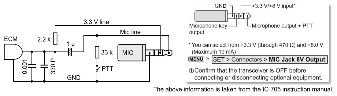 If this information is accurate, the ground side of the mic and PTT is the sleeve on the mic, the PTT button is the TIP and the mic is the RING.. so, making an adaptor that places the 0.001uF and 330pF across the RING and SLEEVE, connecting the 2.2K resistor to ring on mic and Ring1 on IC-705, a 1uF cap from ring on mic to TIP on 705, and to a 33K resistor that connects to TIP on mic should do the trick. |
|
Re: Available Hand Mics for QMX SSB ?
It will take more circuitry than just connections. The 705 has the phantom power separate from the mic+ line and the PTT connected to the mic+. That is completely different from how QMX works, where phantom power for electret is present on mic+ and PTT is separate contact. You'll probably need a couple resistors and a capacitor or two in an adaptor box. |
|
Re: Qmx ft8 linux
Thanks for the heads-up Larryk. Every bit of information helps. I find that in the heat of the moment, when out in the field and something doesn't work as you expect, it's hard to think logically and rationally when trying to figure out which of the hundreds of things that affect settings needs to be tweaked or changed.? |
|
Re: SWR and PWR does not show lcd
So there is definitely some sort of defect here.?
But myself and many others don't experience it (some are seeing wildly swinging SWR), so it must be related to something else in your specific firmware/hardware or configuration, and Hans will likely need more information to be able to find/fix it.
A couple of things I would try, if you haven't already, which have a possibility of getting it to work:
- Just turn off the pwr/swr display option, exit the menu, then go back in and turn it on again.? This could potentially clear something that wasn't fully set properly - then see if it starts working.
- Do a 'factory reset' to bring all settings back to factory default, then turn on the pwr/swr display option and see if it works.? Of course this will undo any settings you have put in, so you may want to record them so you can easily put them back in.? Note that a firmware upgrade does not change any of the compatible settings, so there is some possibility that something set errantly in your eeprom before a firmware upgrade did not clear, and contributes to this problem.
?
Other than that, I'm out of ideas for this strange behavior...
Stan KC7XE |
|
Does anyone else hear this constant 750 Hz square wave through the speaker while the QMX transmits a CW, FSKCW or WSPR beacon message only when the QMX is in USB or LSB mode?
While the QMX is in CW or DIGI modes the speaker remains silent during beacon transmissions . Watch my video at
QMX+ transceiver with Firmware 1_01_003 ?
?
?
?
?
?
? |
|
Peter,
?
Access to the keyer speed control regardless of QMX mode setting is useful if you use the QMX in CW or FSKCW Beacon mode.
?
Carol KP4MD
?
On Sat, Mar 22, 2025 at 04:16 AM, Peter OM4AEI wrote:
3. Short press of left button bring up keyer speed in SSB. Does not make much sense ? |
|
A couple of us ZL hams intend starting a limited group buy for the boards only and will ship within New Zealand only. On Tue, 4 Mar 2025, 02:02 Dean, N2TNN via , <N2tnn=[email protected]> wrote:
|
|
Re: QMX+ points A continuity check to ground question
Steve, that continuity check is not meant to be from points A to ground, it is between pairs of points A.? Two of the points A are BS170 drains, the other is one end of L502.? Checking pairs of these will show zero ohms if the coil soldering is good.? Bad soldering will show high ohms between one or more pairs.? Same goes for the two points B.
?
Checking between each of those points and ground without the coil installed -
In the case of each of the two left-hand A points, without the coil installed, you are measuring the drains of pair of BS170 mosfets whose source is grounded.? Since these mosfets have an internal protection diode between source and drain, if you put your multimeter in diode-check mode, with the red terminal on ground and the black terminal on one of the points A, you should see the 0.6V or so diode drop.? With the probes the other way around, it should show open.
?
For the right-hand A point, you should likely see something a bit different.? You are measuring through coil L502 through a pair of resistors to ground (R525,R526), about 57Kohms.? But you are also measuring (in parallel) through another mosfet source-drain (Q507) to +12V, which should show a different resistance depending on the polarity of your probes, due to its internal diode.? Sorry I can't do this measurement to say what it should be, since I currently don't have a card without the coil installed.
?
I hope that was a little helpful, and you can find your issue.
Stan KC7XE |
|
GPS module GY-GPSV3-NEO wont change baud!
HELP! I need to change my QRP Labs GY-GPSV3-NEO module, which has the UBlox NEO-7M-000 chip on it to 4800 baud, the old NMEA 0183 standard for the TinyTraker3 APRS units.
I can use the UBlox u-center25.03 and everything I receive and send from it appears to work, telling me that the RS232/TTL interfaces that I try are correct. However, going into Messages View - UBX - CFG - PRT - TragetUART1 (or any other) setting BAUDRATE to 4800 and hitting the Send button makes NO CHANGE (EVER). It stays at 9600 Baud! Is there another way to try this and make the change permanent? Perhaps there is an inhibit connection on the chip? Or some sort of authorization command? Connecting a terminal program gives me the continuous GPS strings so the module is correctly putting out my location etc., so that part is also working fine (at 9600). I appear to be stumped! Miniature GPS units running at 4800 Baud are pretty rare and I want to resurrect my Altoids Box Pocket Tracker with one to make it truly pocket size, again. Thanks for any advice or help. 73 - Mike VE3EQP .....> |
to navigate to use esc to dismiss