
Keyboard Shortcuts
ctrl + shift + ? :
Show all keyboard shortcuts
ctrl + g :
Navigate to a group
ctrl + shift + f :
Find
ctrl + / :
Quick actions
esc to dismiss
Likes
- BITX20
- Messages
Search
|
Thank you, Raj, for useful information as always.
One point that has not been brought out for the LID/LIR combination is that most LIR (if not all) are logarithmic in response.? That would more closely match an audio taper pot that would require a complex circuit to get the same log response.? If this is in error please let me know. 73 Evan AC9TU |
|
A variable pot is shown with an arrow. A pot that is adjusted once and
set
toggle quoted message
Show quoted text
is called a preset and is shown with a short line instead of arrow. 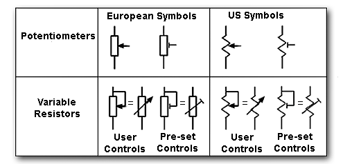 ?
?At 20/11/2020, you wrote: "what component is P1" ????? |
开云体育Vk3ye demonstrates the circuit for the led/ldr combo. I’ve built it and it works to cut high audio peaks?On 19 Nov 2020, at 00:38, iz oos <and2oosiz2@...> wrote:
|
|
AGC is a feature and attenuation is a function. Automatic Gain control can work using an electronically controlled attenuation in the signal chain or by using variable gain amplifiers somewhere in the chain. the golden rule of good signal processing is to control the gain as early in the signal chain as is possible. The best gain control is to put variable resistor right at the antenna terminal. The reason is very simple: the amplifiers down the chain have to handle weaker signals and weaker signals mean better fidelity. An audio AGC in a conventional superhet where most of the gain is in the IF stage will overload even on a moderate signals due to the distortions in IF amplifiers. Picture this, there is the lowest level signal that the receiver can resolve, this is set by the bandwidth and the noise figure of the receiver. The? highest signal that the receiver can resolve without distorting is determined by the IIP3 and the phase noise of the local oscillator. The range of signals between the minimum discernable signal and the loudest signal that the receiver can handle without noticeable distortion is your dynamic range. Now, consider what happens if you switch on a 10 db attenuator between the antenna and the receiver. the MDS (minimum discernable signal) has to be 10 times more powerful and on the other hand, the signal level at which the distortion starts to show is also up by 10 db. In effect, to borrrow?Rob, NC0B's words, the dynamic range is a moveable window that can be shifted up or down with attenuators. Most receivers are too sensitive for HF bands. For instance, the ubitx is too sensitive for 40 meters, the atmospheric noise is 100 times more powerful than the internal noise (noise floor) of the receiver. This is wasted dynamic range. if we had thrown in a 20 db attenuator, we would hear exactly the same signals as before but our dynamic range would have been 100 times more. Dynamic range doesn't only apply when you are contesting or having a neighbour who transmits 1000 watts, it is a measure of how sweet the receiver sound is as well. So, why is ubitx so needlessly sensitive? That is, because it is meant to work from 10 meters to 80 Meters. That sensitivity will be needed when the 15 meter opens up in a few years from now. RF attenuation does remain the best place to control the gain, even for an AGC system. The challenge is to build a smoothly varying attenuator that doesn't need any active devices. Active devices in wide open receivers like the ubitx can severally compromise the receiver performance.? I am planning to do a video to explain who careful gain distribution is the key to a good radio design. - f On Fri, Nov 20, 2020 at 9:38 AM TD <dlee@...> wrote: > "what component is P1" ????? |
|
TD
"what component is P1" ?????I figured it was a pot but never seen that symbol used before. --- Darrell Lee Advanced Data Systems, Inc. 2801 Wade Hampton Blvd. Suite 115-153 Taylors, SC 29687 864-230-9626 | dlee@... On 11/19/2020 01:15 PM, IW4AJR Loris wrote: Hello TD ... |
|
Re: Alternative Calibration Procedure uBITx v6
Repeat the same on other time signals such as 10 15mhz and beyond when propagation is in a good mood Il gio 19 nov 2020 04:13 AM Mark Erbaugh <mark.election@...> ha scritto: Following the calibration procedure for my v6, I had trouble zero beating a carrier, so I tried a modified approach that seems to work better for me. With the radio in LSB mode, I tuned 1 kHz above WWV at 5 MHz. WWV's carrier thus creates a 1 kHz tone. I used a program with an audio waterfall (I used FLDIGI) and adjusted the uBITx's tuning calibration until the tone was at 1 kHz. |
|
Re: Alternative Calibration Procedure uBITx v6
IW4AJR Loris
Hi Mark
Finally someone using a "lab" approach to calibrate a receiver!
Great approach!
For the wealthiest:
1) fix a frequency on the receiver in LSB,
2) fix the frequency of the RF generator 1kHz above the chosen frequency,
3) connect a frequency meter to the audio output,
4) act on the calibration until reading exactly 1kHz !
Easier than that ...!
Great job Mark ! thanks ! greetings Loris IW4AJR |
|
IW4AJR Loris
Hello TD ...
"what component is P1" ????? maybe it is simply a resistive trimmer or a potentiometer ???? perhaps !!! HAHAHAHA
?
don't tell me you don't know what P1 is because I don't believe it!
?
this diagram is just an example of how a simple dynamic compressor with a handful of passive components can be made, how to insert it and where to insert it in the ?BITX is something you have to decide, study it a bit and look at the diagram of the part receiver of the ?BITX (from the volume potentiometer to the speaker) and see if you need it as an input to the BF amplifier (LM386) or if you want to insert it in parallel with the output before the headphone jack.
?
hi TD ... good job! greetings from IW4AJR Loris |
|
TD
What component is P1? Where in a transceiver would one connect this circuit?
toggle quoted message
Show quoted text
Thanks, --- Darrell Lee Advanced Data Systems, Inc. 2801 Wade Hampton Blvd. Suite 115-153 Taylors, SC 29687 864-230-9626 | dlee@... On 11/19/2020 10:27 AM, IW4AJR Loris wrote:
Hi Bob, |
|
Re: GPSDO ubitx ?
I also forgot to mention the project from Scullcom.uk for a 10Mhz reference oscillator. Granted it is designed to be more of a bench reference, but I'm sure you could accommodate for that! His project is based on the Neo 7m for reasons he describes in the video. I've not seen many of those around so if you wanted to do this project you may want to look for the Neo 8M/N or other newer variants that have the 10Mhz capability. ? http://www.scullcom.uk/category/projects/frequency-reference/ |
|
IW4AJR Loris
Hi Bob,
?
If you want to try out an "ancient" headphone dynamics compressor, known to QST readers in the 60s, you can try the attached diagram.
?
The attached simulation is done with LTspice, the values are a little different because I have simulated different solutions, but the substance does not change ... "IT WORKS" !!! ...
P.S. the simulation is done by combining 3 frequencies (300Hz, 1.650Hz and 3.000Hz) to see the behavior in the normal OM reception range and check for any harmonic distortions introduced, the result is excellent, from the FFT the only harmonics present are over 5kHz , in an area where they should not give distortions.
?
Good experiments and a dear greeting from IW4AJR Loris |
|
Re: GPSDO ubitx ?
Dear Ashhar,
toggle quoted message
Show quoted text
Thanks a lot for the detailed solution. The two ubitx are arriving soon home, I'll try to replicate here, I have a GPSDO with a 10MHz output. Rafael On 11/19/20 12:48 AM, Ashhar Farhan wrote:
I tried something a year ago or so. I was attempting to reduce the |
|
IW4AJR Loris
Hi Bob,
?
why go crazy to try and try to invent hot water?
?
In HiFi amplifiers, the problem of ear protection in headphones has already been solved for almost a hundred years! just make a resistive divider on the output with two resistances between the signal (positive pole of the speaker) and ground (120Ω / 1W + 56Ω / 1 / 2W) and that's it, have you ever skipped eardrums listening to a vinyl ad high dynamics with headphones? if you love listening to Classical Music, sudden changes from a pianissimo to a fortissimo are the order of the day!
Look at the attached diagram, it is taken from a SUPERSCOPE A-260 from the 70s ... there are so many things to experience on the ?BITX without getting lost in things that have already been solved for decades!
Good experiments and a dear greeting from IW4AJR Loris |
|
IW4AJR Loris
Hello "iz oos",
normally a vogad, such as the SL6270 or similar, is used as a dynamics compressor for microphone input, obviously, with the appropriate checks of in / out levels and coupling impedances, nothing prevents it from being used even in a BF circuit to control the level output in the speaker or headphones, I just wonder if it's worth it, the cost will certainly be higher than a coupled LED / photoresistor that can give equally valid if not better results.
The advantage of the audio compression system that gives an LED / photoresistor circuit is the flattening of the dynamics practically independent of the input frequency (obviously within the limits of the LED's ability to react to high frequencies) on a much greater frequency spectrum than a chip vogad, this allows to keep the frequency response of the BF amplifier circuit intact.
Also consider the simplicity of the circuit (see the two attached diagrams), to add a LED / photoresistor compressor in the ?BITX just insert the circuit between the output and the negative input of the LM386 and that's it.
Best wishes from IW4AJR Loris |
|
Bob
That was kind of what I expected, call it 3 or maybe even 6 dB, but perhaps you think a bit less. Now if you had a photoresistor, I find these can suppress a signal around 20 dB. Amazing to me being resistive material, relative to light energy, it works without apparent distortion.? It cannot free us from needing to use a volume control, but its what i was seeking. Let there be light, dampening the signal chain. Or if one must have real agc, go to work in the IF signal chain. But cool this scheme merely wires to the volume control. 73 curt |
|
I tried the scheme with two computer switching diodes from the earphone lines to ground and it does work although not as effectively as I'd hoped. I'll prepare a headset to do this for me and I expect it to still work as designed with other applications. May have to change the connector, though, to avoid cutting the headphone line. Bob — KK5R
On Thursday, November 19, 2020, 2:12:45 AM EST, Bill Cromwell <wrcromwell@...> wrote:
Hi, I have done and will be doing it again. When very loud signals suddenly appear in the cans, instead of making your ears bleed you will hear it suddenly very distorted and maybe a little louder. That is your cue to turn down the volume. It won't function like the AGC you are used to. It will protect your hearing. 73, Bill? KU8H bark less - wag more On 11/18/20 7:56 PM, Bob Lunsford via groups.io wrote: > For headphones, I wonder if two diodes with polarities reversed from > each other across the headphone line would provide some hearing > protection...? Or a pair of reversed polarity in series if the volume > were affected too much. Does this cause severe distortion? (I've read > about doing this but never tried it.) > > By the way, what is "vogad"??? > > Bob — KK5R > > On Wednesday, November 18, 2020, 7:38:16 PM EST, iz oos > <and2oosiz2@...> wrote: > > > Loris, would you think a vogad at the audio output could be a solution > to save both sensitivity and hears to some extent? > > Il mer 18 nov 2020 06:10 PM Arv Evans <arvid.evans@... > <mailto:arvid.evans@...>> ha scritto: > >? ? AAT (Automatic Attenuator Control)? >? ? _._ > > >? ? On Wed, Nov 18, 2020 at 5:32 AM Bill Cromwell <wrcromwell@... >? ? <mailto:wrcromwell@...>> wrote: > >? ? ? ? Hi Loris, > >? ? ? ? There are a lot of newbies here and they just don't know. Don't be >? ? ? ? angry. Just help them alomng if they are actually open to help. I >? ? ? ? started learning about physics and electronics in the early >? ? ? ? 1950s and I >? ? ? ? still don't everything. I am more and moire aware of how much I >? ? ? ? don't >? ? ? ? know. I usually do know where to look:) > >? ? ? ? 73, > >? ? ? ? Bill KU8H > >? ? ? ? bark less - wag more > >? ? ? ? On 11/18/20 7:17 AM, IW4AJR Loris wrote: >? ? ? ? ? > Hi Bill ... I fully agree with you! >? ? ? ? ? > What I am wondering is "why" this forum continues to call AGC >? ? ? ? a very >? ? ? ? ? > vulgar "ATTENUATOR" even if more or less automatic. >? ? ? ? ? > 73 Loris >? ? ? ? ? > > > > > > > |
|
Re: Typo in ubitx_v6.1_code.ino?
Hi Mark,
You're correct about CW mode not being a persistent setting in the stock software. No reason you couldn't save it somewhere, though. I don't recall about stock, but I know my software saves on side band change and VFO switch, so if I want to save the frequencies I'm on, I just press one of those buttons. TSW's teensy software periodically saves, so if you stay on a frequency for a bit, then power off, it will have automatically saved at some point prior. Since the power is controlled by a knob that the uC has no connection to, it's not possible to "gracefully" shut down, unless you do some hardware mods. Reed |
|
Re: Typo in ubitx_v6.1_code.ino?
Another question on the code. It seems like the radio does not save the CW state to EEPROM, just USB or LSB. Is this correct? In testing with my radio, I turned on CW and changed bands (so the frequency was saved to EEPROM) and did a power cycle, the CW state was not restored.
BTW, what triggers a save of frequency to EEPROM? If I use the tuning knob to adjust the frequency and power cycle, the frequency returns to what it was before I changed it. I understand that due to the limited write cycles of the EEPROM, you don't want to be writing the frequency every time it changes. I also don't see a way to have the radio detect a shutdown as the power is abruptly turned off. 73, Mark |
|
Curt, I just tried two 1N914 type diodes connected anode-cathode and placed it across the earphone lines to ground. I tuned to a net where there were several hams with one really loud and the others weaker. The diode arrangement did help to the extent that while the loud station was still loud, it was not booming in my ears. If I had to guess, the signal in the headphones was about half what it was and it was livable. Therefore, it does help and I did not have to chase the volume control to keep the net comfortable as I did without the diodes. The headphones were the common, 32 Ohm type. I'd call it a clipper, a "leveler" or an equalizer but not an attenuator. Ha It does not serve as a type of AGC but better if it is considered a crude safety device to help save the ears until something better comes along. Bob — KK5R
On Wednesday, November 18, 2020, 8:30:24 PM EST, Curt via groups.io <wb8yyy@...> wrote:
Bob I have seen that method used -- so give it a try if you have a pair of diodes handy.? I am trying to recall which rig I saw this used with.? silicon may work - but maybe some folk may use germanium or schottky - try what you have.? At least with my v4, I am not hearing signals that would blast me out of the chair.? Its just a matter of 'enjoying tuning across the band.? If you have a photoresistor handy, then find an LED and a couple NPNs to try the circuit I recommend.? Otherwise, who knows see what the diodes will do.? cool thing about the ubitx - 'have it your way' -- no reason not to be counter-culture.? forgive me for liking the dancing LED inside my ubitx case.? enjoy your listening and radiations.? Curt |
|
Re: GPSDO ubitx ?
I tried something a year ago or so. I was attempting to reduce the phase noise on Si5351 using an external oscillator instead of the internal oscillator. So, this is how it worked.? 1. You take a 10 MHz TCXO, (subsitute this with a GPS source for a GPSDO) and divide it by 2 in a 74HC74. The output is rich in harmonics at 5 MHz. 2. You feed the 5 MHz square wave into a triple tuned bandpass filter at 25 mhz to isolate the 5th harmonic. This will be weak, add an amplifier of 16 db to bring it up. 3. Feed this to the xin input of the Si5351. Now, your Si5351 is GPS disciplined. On Thu 19 Nov, 2020, 7:35 AM Rafael Diniz, <rafael@...> wrote: Very interesting Jason! Tks! |
to navigate to use esc to dismiss