
Keyboard Shortcuts
Likes
Search
What is with this trace? (Lavalier Teardown: Shure WL185 with RF CommShield)
|
When cell phones became common, Shure lavalier microphones were picking up GSM noise. Shure changed their FET circuit, added a dot on the lavs so you'd know they're the new type and marketed them as having " Technology for RF Filtering". I was curious about the circuit so I opened up a Shure . The family of lavs (WL185, WL184, WL185) have interchangeable 10mm-ish capsules (cardioid, supercardioid, omnidirectional) and are very popular for sound reinforcement applications.
Here is the circuit I traced: a few caps (not 100% sure of values, but they should be close to what is below), a SMD ferrite bead, no real surprises in the schematic apart from the 100 ohm resistor which actually increases the output impedance of the mic. I believe R1 is to allow the caps to kick in from a lower frequency, any other ideas? The real surprise, however, is the PCB layout. The source terminal of the JFET is routed as a ring trace all around the gate terminal capsule connector, on both sides of the board! Is this FET circuit using PCB losses to bias Vgs instead of a large value resistor (or, as would be expected for a small electret, back-to-back diodes)? Or is it RF magic? To me it seems that the first one is more likely: the trace is a full ring around the capsule terminal, routed with minimal clearance. Any other explanation? Identifying the FET would help, but it has no marking. |
开云体育It's sometimes called electrostatic guard. A very common technique in RF and very high impedance circuits. The parasitic capacitance is used profitably to bootstrap the
gate. It shields the gate as much as a ground pour but without the
detrimental effects of parasitic capacitance. Le 09/06/2024 à 20:06, sergio_logic via
groups.io a écrit?:
When cell phones became common, Shure lavalier microphones were picking up GSM noise. Shure changed their FET circuit, added a dot on the lavs so you'd know they're the new type and marketed them as having " Technology for RF Filtering". I was curious about the circuit so I opened up a Shure . The family of lavs (WL185, WL184, WL185) have interchangeable 10mm-ish capsules (cardioid, supercardioid, omnidirectional) and are very popular for sound reinforcement applications. |
开云体育R1 is to bias the Fet properly. Also there is no 1G resistor as that Fet has an internal diode designed to “leak” current and somewhat act as the 1G resistor. Most electrets with built in FETs have that too.?Best Regards, Jules Ryckebusch? On Jun 9, 2024, at 13:19, sergio_logic via groups.io <sergiu757@...> wrote:
|
|
Thanks for the answers!
The the Shure bodypacks have a 20KOhm bias resistor to ground where I wrote “BODYPACK_20K_BIAS_AND_AUDIO”. What difference does 100Ohms make? It’s a 0.5% difference, probably less than the tolerance of that 20K resistor. This is why I doubt it has any relevant impact on the Q-point of the FET. |
|
The effect of R1 on the bias point is indeed negligible compared to the 20k source resistor load. I think R1 is there to avoid ringing or even parasitic oscillations caused by the capacitive load of C1 and the parasitic inductances from the PCB tracks and capsule. Similar to emitter followers, which you want to decouple from capacitive loads through a resistor for the very same reason.
Jan |
|
Update on the FET: I removed the capsule from another one and it's marked "IA". I believe it's a Toshiba TTK101MFV, datasheet states it's for "compact ECM" and the equivalent diagram shows a bias diode (and resistor, but that's not real, its "equivalent", it's not possible to integrate large value resistors).
|
|
Digression on wireless beltpack connectors...
toggle quoted message
Show quoted text
The Shure TA4F (aka mini-XLR) wiring scheme is pretty clever - you can wire it for different topologies as the audio and power pins are separate. The 20k resistor pin is there to provide a DC return path when needed. The basic pinout is: 1 - ground 2 - DC +5v 3 - Audio 4 - 20k resistor to ground Note that the mini-XLR pin #s are not the same as regular sized XLR! A lot of other wireless manufacturers put both power and audio on the same pin, as do a lot of the lavalier mics.? Sennheiser does that on the high-end LEMO connector versions, which means that if you want to use a guitar cable you have to add a DC-blocking capacitor.? Their cheaper Evolution line uses 1/8", and the ring contact is an audio-only input with no power.? Shure's implementation of the same 3-pin LEMO connector is compatible but slightly more complex. I'm a pretty serious pinout nerd in that world, if you need info please feel free ask. -Scott On 6/9/24 21:43, sergio_logic via groups.io wrote:
Thanks for the answers! --
---- Scott Helmke ---- scott@... ---- (734) 604-9340 ---- "I have ceased distinguishing between the religious and the secular, for everything is holy" - Joe Henry |
|
Hi Scott,
I'm a pretty serious pinout nerd in that world, if you need info please feel free ask.I'm going to take you up on that offer. I don't know if you are familiar with Sony UWP bodypack wiring (it's probably less popular than Shure/Sennheiser in the US, whereas in Europe it has a pretty fair share with Sennheiser in the TV studio market) Sony UWP uses 1/8" (3.5mm) TRS jack with the following wiring: Tip - audio and 7k/9k Ohm bias resistor to ground (varies a bit among generations, UTX-B03/B40 are 7K, old UTX-B2 is 9K) Ring - 5V (through ~330 Ohm current limit resistor) Sleeve - GND Now, knowing this pinout, how would you go about connecting a DPA 2-wire lavalier to Sony UWP?? DPA this: "DPA miniature and subminiatures should never be connected to a compensational circuitry as it may reduce the already optimized output. In the adapter connection scheme of DAD6010 (MicroDot to 4-pin connector) which is shown below, pin 4 (for active load) is not connected." -- so in the case of the Shure pinout you mentioned, they make a point about NOT connecting the load resistor. Yet, their $105 adapter DAD6019, listed as with Sony UWP, does exactly that, it's just a 3k3 ohm resistor from 5V to Tip (audio and 7K to ground). This means, that even under no load, the voltage at the microdot is ~3.3V = 5V*7K/(7K+3K3+0K33), as measured .  What happens if the voltage is below 5V for these mics spec'd for at least 5V? DPA answers : "As mentioned, the output signal depends on the supplied DC voltage. If it is too low, it may result in asymmetrical clipping of the audio signal above a certain level [see figure 4]", and "If the available bias voltage is, say, 4 or even 3 volts, the microphone still works. But the acoustical input must be reduced and kept below a limit, lower than the usually specified max SPL; this is to avoid distortion." 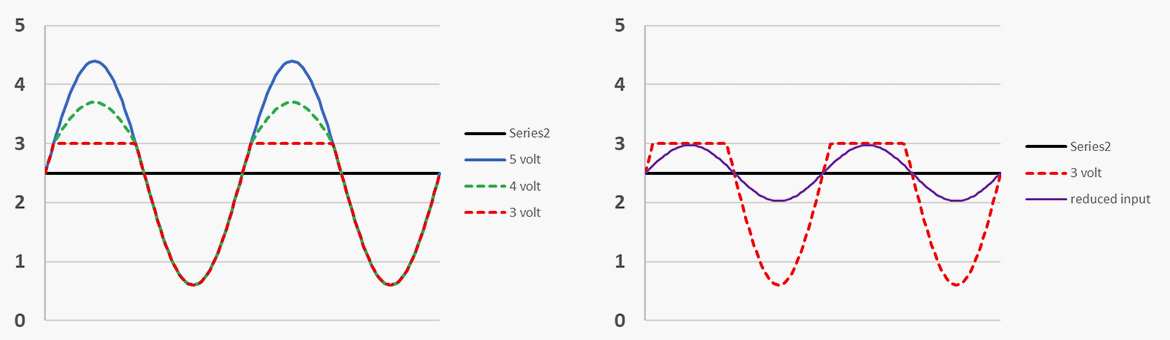 This is precisely what happens with the DPA DAD6019 adapter, although DPA mentions no max SPL limitations introduced by the adapter: I've made my own adapter which biases the mic through a 3K3 (metal film) resistor between the 5V and the mic wire (as all the adapters for the 5V systems do), but then only AC couples it to the Tip (SMD tantalum, anode at mic), effectively removing the Sony's 7K resistor from the DC bias. The build quality is not like the DPA, but it's not $105 either. Of course, this fixes the positive swing issue: (Note, my "sound source", an iPhone loudspeaker, was distorting the sine, not the mic.) I wrote all this to DPA ~1 year ago, they replied but only said they will investigate. They have not updated the schematic of the DAD6019 in the meantime. So, do you think there is another way around this? My "A-frame" made of a cap and resistor is not the most mechanically sound solution, but it seems electrically correct. |
|
Le 12/06/2024 à 11:01, sergio_logic via groups.io a écrit?:
DPA seem to be looking down at external contributions. I wrote them about a misconception in their "condenser vs. dynamic mics" Mic University discussion. They answered, even the junior engineer that had written the article, but they never correct the article. |
|
First off, the DPA mics are great mics and currently the pro standard, though they are kind of in phase 2 of this sort of product - packaging and marketing to sell as many as possible. I don't know if they do a lot of testing of all the generations of wireless their adapter might connect to.
toggle quoted message
Show quoted text
Also I'd call the DPA wiring a "single conductor" because the shield isn't really considered in that terminology.? A "two wire" lav would have two conductors inside the shield, and in the case of some Shure lavs the shield is just a shield and is not part of the mic circuit. Anyway, it seems like a simple enough problem.? You want the FET in the mic capsule biased correctly, and its bias point is in the middle of a voltage divider made up of all the resistors between the power source and ground - so 330 ohm plus 3.3k ohm from +5, then that 7k ohm to ground. Since the FET draws a tiny amount of current, you might just want to *increase* the 3.3k resistor to match the 7k resistor.? Sennheiser lavs usually use an 8.2k resistor, for example. So that's what I've got time for this morning before I go to work. I haven't actually tried this myself, but I'll check my file for any pinouts for that Sony wireless. -Scott On 6/12/24 04:01, sergio_logic via groups.io wrote:
Hi Scott, --
---- Scott Helmke ---- scott@... ---- (734) 604-9340 ---- "I have ceased distinguishing between the religious and the secular, for everything is holy" - Joe Henry |
|
Of course as soon as I started brushing my teeth I noticed the mistake... I'm not accounting for whatever resistance is in the capsule carrying DC to ground to complete the circuit.
It'll have to wait a day, but I do actually have the means to measure that resistance directly and there's a suitable victim on my bench at the moment. -Scott On 6/12/24 07:47, Scott Helmke wrote: First off, the DPA mics are great mics and currently the pro > standard, though they are kind of in phase 2 of this sort of product - packaging and marketing to sell as many as possible. I don't know >if they do a lot of testing of all the generations of wireless their > adapter might connect to. > > Also I'd call the DPA wiring a "single conductor" because the shield > isn't really considered in that terminology. A "two wire" lav would > have two conductors inside the shield, and in the case of some Shure > lavs the shield is just a shield and is not part of the mic circuit. > > Anyway, it seems like a simple enough problem. You want the FET in > the mic capsule biased correctly, and its bias point is in the middle > of a voltage divider made up of all the resistors between the power > source and ground - so 330 ohm plus 3.3k ohm from +5, then that 7k > ohm to ground. Since the FET draws a tiny amount of current, you > might just want to *increase* the 3.3k resistor to match the 7k > resistor. Sennheiser lavs usually use an 8.2k resistor, for > example. > > So that's what I've got time for this morning before I go to work. I > haven't actually tried this myself, but I'll check my file for any > pinouts for that Sony wireless. > > -Scott please feel free ask. >> >> I'm going to take you up on that offer. I don't know if you are >> familiar with Sony UWP bodypack wiring (it's probably less popular >> than Shure/Sennheiser in the US, whereas in Europe it has a pretty >> fair share with Sennheiser in the TV studio market) >> >> Sony UWP uses 1/8" (3.5mm) TRS jack with the following wiring: Tip >> - audio and 7k/9k Ohm bias resistor to ground (varies a bit among >> generations, UTX-B03/B40 are 7K, old UTX-B2 is 9K) Ring - 5V >> (through ~330 Ohm current limit resistor) Sleeve - GND >> >> *Now, knowing this pinout, how would you go about connecting a DPA >> 2-wire lavalier to Sony UWP? * >> >> DPA mentions >> <>this:On 6/12/24 04:01, sergio_logic via groups.io wrote: >> Hi Scott, >> I'm a pretty serious pinout nerd in that world, if you need info >> compensational circuitry as it may reduce the already optimized >> output. In the adapter connection scheme of DAD6010 (MicroDot to >> 4-pin connector) which is shown below, pin 4 (for active load) is >> not connected." -- so in the case of the Shure pinout you >> mentioned, they make a point about NOT connecting the load >> resistor. >> >> Yet, their $105 adapter DAD6019, listed as compatible >> <>with"DPA miniature and subminiatures should never be connected to a >> to Tip (audio and 7K to ground). This means, that even under no >> load, the voltage at the microdot is ~3.3V = 5V*7K/(7K+3K3+0K33), >> as measured here <>. >> >> >> What happens if the voltage is below 5V for these mics spec'd for >> at least 5V? DPA answers here >> <>:Sony UWP, does exactly that, it's just a 3k3 ohm resistor from 5V >> voltage. If it is too low, it may result in asymmetrical clipping >> of the audio signal above a certain level [see figure 4]", and "If >> the available bias voltage is, say, 4 or even 3 volts, the >> microphone still works. But the acoustical input must be reduced >> and kept below a limit, lower than the usually specified max SPL; >> this is to avoid distortion." >> >> >> This is precisely what happens with the DPA DAD6019 adapter, >> although DPA mentions no max SPL limitations introduced by the >> adapter: >> >> >> I've made my own adapter which biases the mic through a 3K3 (metal >> film) resistor between the 5V and the mic wire (as all the adapters >> for the 5V systems do), but then only AC couples it to the Tip (SMD >> tantalum, anode at mic), effectively removing the Sony's 7K >> resistor from the DC bias. >> >>"As mentioned, the output signal depends on the supplied DC >> "sound source", an iPhone loudspeaker, was distorting the >> sine, not the mic.) >> >> I wrote all this to DPA ~1 year ago, they replied but only said >> they will investigate. They have not updated the schematic of the >> DAD6019 in the meantime. >> >> *So, do you think there is another way around this?* My "A-frame" >> made of a cap and resistor is not the most mechanically sound >> solution, but it seems electrically correct. >> >The build quality is not like the DPA, but it's not $105 either. Of course, this fixes the positive swing issue: >> >> >> (Note, my -- ---- Scott Helmke ---- scott@... ---- (734) 604-9340 ---- "I have ceased distinguishing between the religious and the secular, for everything is holy"? - Joe Henry |
|
Thanks for the answer. |
|
The Audio-Technica patent is . In the context of XLR gooseneck microphones they are disclosing this JFET-PNP topology as the "front end"/"head":
As depicted, it's not the easiest thing to bias properly, but if you balance the currents between the JFET such that the FET is limited at ~60uA and the rest is handled by the PNP, you get a V(I) curve that looks something like this: At low currents the JFET is conducting and you get a linear segment, when the JFET current gets limited, the PNP starts to turn on and you basically have a PN junction on top of a fixed Vs (fixed because the current through the JFET is constant, so Vs is this current times R1). And this is what real measurements for DPA CORE look like. Past 0.2mA, the DPA is actually flatter than a PN junction: at 0.25mA it measures 2.622V, at 0.8 mA it measures 2.628V, a delta of only 6mV, whereas the JFET-PNP simulation shows a rise of 40mV over the same current range (as expected for a PN junction). So I think the DPA likely has more transistors and some feedback to keep the FET's Vds constant to a precision better than a Vbe. This very simple topology also bootstraps both the source and the drain, so the effects of both Cgs and Ggd are minimized (within the variation of the Vbe of the PNP). The operating point that most of DPA's adapters would set for this mic is around 0.65mA (except the one for Sony UWP, which puts it at 0.28mA instead!). It's easier to bias if we split R1 into a voltage divider (like Schoeps and Pimped Alice do with the 1Meg pot). Because gate leakage is negligible vs. the 60uA target, and gate leakage is the only DC current through R3, for the purpose of choosing R1 we can consider R3 = 0, which turns J1 and R1 into a familiar . So R1 can be chosen just based on the JFET (it correlates with the pinch-off voltage, Idss only has an impact if Idss is not much larger than 60uA). Then, we set the target output DC operating point for Vd by choosing R2 to "lift" Vs (and Vd because Vd = Vs + Vbe). The current through R2 is the same 60uA, so this is easy. For something that would operate with similar voltage as DPA CORE, the JFET just needs to have a pinch-off voltage in the -0.3V to -1.5V range would work, the rest is up to R1 and R2. I'm not saying DPA needs to match resistors to the JFET, although at a $600+ price point they probably could (and the procedure for selecting the resistor value based on the JFET lends itself well to automation), but it's also likely that the extra "silicon" they mentioned in their press release has something to do with setting the JFET operating point. But an amateur builder can certainly select a couple of resistor values based on the method above. |
|
OK, so I happened to have a DPA 4066 headset capsule on my bench - I work for a company that rents out audio gear, including a lot of wireless with DPA mics. So this one showed up as unrepairable due to the wire connection failing.? The mic itself is still good (well, maybe not after this much disassembly) and I've rescued a couple others in the past as experiments.
toggle quoted message
Show quoted text
This is the standard DPA omni lav/headset capsule - yes it's square!? The wavelength of 20k is longer than these dimensions so no issues with that.? What you can see on the bottom is a 3-pin SMD device, presumably a FET. Where the wire connects there is what should be a small capacitor to shunt RF, and on the other leg is a resistor - 33k ohms to ground.? The pin on the perforated side would then have to be the gate of the FET, connecting to the diaphragm. I'm not sure how biasing is done. -Scott On 6/12/24 08:21, sergio_logic via groups.io wrote:
--
---- Scott Helmke ---- scott@... ---- (734) 604-9340 ---- "I have ceased distinguishing between the religious and the secular, for everything is holy" - Joe Henry |
|
As somewhat expected, the photos disappeared.
toggle quoted message
Show quoted text
The album can be found here: /g/MicBuilders/album?id=295709 -Scott On 6/14/24 20:42, Scott Helmke wrote:
OK, so I happened to have a DPA 4066 headset capsule on my bench - I work for a company that rents out audio gear, including a lot of wireless with DPA mics. So this one showed up as unrepairable due to the wire connection failing.? The mic itself is still good (well, maybe not after this much disassembly) and I've rescued a couple others in the past as experiments. --
---- Scott Helmke ---- scott@... ---- (734) 604-9340 ---- "I have ceased distinguishing between the religious and the secular, for everything is holy" - Joe Henry |
|
Thanks, Scott. The only reasonable images of the DPA CORE "preamp" (their word) is from a , where they also say each one is "tuned to match its capsule".
Looks like a bunch of tiny SMD components (many of which are leadless packages!) on a tiny PCB. I have an educated guess about the amplifier topology because it quacks like a duck: if U(I) looks like a voltage regulator, it's a voltage regulator at DC. Like I said before: Past 0.2mA, the DPA is actually flatter than a PN junction: at 0.25mA it measures 2.622V, at 0.8 mA it measures 2.628V, a delta of only 6mV, whereas the JFET-PNP simulation shows a rise of 40mV over the same current range (as expected for a PN junction).The JFET's Vs is already stable with what I've shown previously (the FET is its own current source in a way, and that current times the resistor is a fixed Vs). They are using feedback to further regulate Vds on top of it. In principle: (Where, in the case of DPA, Vo is driven from 5V through ~3.8K). As depicted, implementing the target Vds with a forward biased diode (or 2, or a LED) in parallel with a cap, this is already a topology that may be used in phantom-powered preamps. Doing it without a power rail higher than Vo, like DPA does, is another story. A bootstrapped 4-transistor long tailed pair (resistor from Vo, PNP inputs, NPN current mirror) as the op amp is something that could work reasonably well. It's bootstrapped because (as long as the feedback works) the PNPs' bases are at Vo-Vds, so the top resistor always sees Vds-Vbe, which is reasonably constant (and turns the "dumb" resistor into a constant current source!). I will probably start another thread going into the topologies. I plan to build a phantom preamp based on the op amp one. |
|
So yeah, I forgot to actually make my real point - what's the current flow for the DC bias? ?What's the best resistor for that Sony wireless, in other words??
It might be a little while before any Core mics happen to cross my bench, but I'll keep an eye out. The DPA headsets and lavs are pretty durable for the application. ?So we'll have to just go off my pre-Core teardown. The 3-pin chip wrapped around the bottom might well be more than just a FET, but it really doesn't matter. The important thing here is that there's the audio/power line on one pin, and a 33k resistor to ground on the other. The third pin will be the super high impedance part and we don't need to worry about it.? So the ? resistor, which DPA usually specifies as 3.3k, should probably be at least twice as high to bias the FET towards the center of the voltage range.? Assuming there's nothing else going on here, like noise performance or something.? You could just connect up a 10k potentiometer in place of the 3.3k resistor and twiddle the knob until you get the best performance, then measure the resistance. Of late I've been a little curious as to why manufacturers specify particular resistor values. This exploration tells me I'm right to be suspicious. -Scott |
|
Le 15/06/2024 à 14:59, Scott Helmke a écrit?:
So the ? resistor, which DPA usually specifies as 3.3k, should probably be at least twice as high to bias the FET towards the center of the voltage range.? Assuming there's nothing else going on here, like noise performance or something.? You could just connect up a 10k potentiometer in place of the 3.3k resistor and twiddle the knob until you get the best performance, then measure the resistance. Actually, biasing the FET for having half the B+ voltage on the drain is not necessarily the best operating point in terms of output drive and headroom, which are improved by increasing current. Hence the lower value of the recommended resistor. |
|
Firstly, I apologize, but I'm too lazy to start a new thread and write an entire introduction covering what was already presented here regarding DPA CORE.
I just want to add what I believe is the DPA CORE topology, based on the ideas above: very stable bias voltage, bootstraps both Cgs and Cgd, low output impedance / emitter follower, the "five times the amount of silicon has been added to the circuitry" from the Dec 2017 press release (five transistors in addition to the JFET is my interpretation), a plausible match for the photos from the video, handles at least 2.25V peak-peak at the output with under 1% THD (based on DPA's spec of 126 dB max SPL and sensitivity of 20 mV RMS at 94 dB / 1 Pa). To the best of my knowledge, this ticks all the boxes: The two smaller and squarer plastic package components could be the PNPs, the other 3 the NPNs:  It works like mentioned before: error amplifier keeping VDS constant. The amplitude of vgs and vds is 20+ dB lower than the amplitude between the gate and ground, so Cgs and Cgd basically vanish, the capsule "sees" less than 0.5pF as the input capacitance of the JFET. The voltage across R9 is also approximately constant, which turns R9 into a current source. I'm not sure about the current split between the 4 branches (JFET, divider, diff pair, output follower). My guess is based on the measured U(I) curve is 50uA, 15uA, 50uA, the remainder, respectively. Same issue regarding the target VDS: I can't be sure, probably around 0.95V. Manufacturing issues: as far as I can tell, a voltage offset caused by transistor mismatch will only change the target VDS by a couple dozen mV, which is not critical. R2 and R1 must be selected based on the JFET: R2 sets the current, R1 sets VS. The actual DPA circuit likely has additional components for EMI filtering. With an op amp as the error amplifier, this circuit may be implemented as an XLR preamp with e.g. OPA1692 (a non-JFET, lower current cousin of the OPA1642 used in OPA Alice), and will offer a smaller input capacitance than OPA1642 (at the "cost" of having a discrete JFET that has to be biased). |
|
@Scott:
Even ignoring the Sony 7K complication, I don't think your diagram is correct. The swing seen at the drain ("to audio input") would be some 20 dB lower than the swing seen at the source, basically wasting all the current gain (transconductance) of the JFET on the 33K to generate a voltage drop between source and ground that the bodypack would not see. The bodypack only sees the voltage drop between 5V and drain. The bias would be very weird as well, as most of the voltage drop would be across the 33K and the audio input pin would sit really close to 5V. I think either the connections are different from your depiction, or the assumption that the plastic package is a JFET is incorrect and even the non-CORE DPAs have something less conventional than a single JFET. My misunderstanding of what's going on is also always a possibility. If you agree that it can't work as depicted, is there any chance you could measure the U(I) curve? There could be some clues there. You can use and identical circuit and just vary the 5V between 0 and 5V and record this voltage (VSRC), as well as the voltage at "to audio input" (VD) in a spreadsheet. The voltage of the mic is VD and the current is (VSRC-VD)/3K6. |