Re: HP-8753E Power Cycles at Start Up
Peter:
While I cannot answer your question directly, the capacitor's in mine are Nippon’s. I have seen those last forever without fault. They were sparing no expense in this department when making the supply.?
Off the top of my head, I can’t think of anything I have seen inside this supply that would short intermittently and then recover.?
I had to leave the office, so I am not in front of the supply any longer.?
toggle quoted message
Show quoted text
On Aug 29, 2022, at 4:18 PM, peter bunge <bunge.pjp@...> wrote:
? With my 'scope on EN of the reset timer I loaded the 5v with an extra 500 mA and the higher voltage supplies with 100 mA. The voltage did not change from the?+3v so it would need a short somewhere to trip this I think. I also blew a hot air gun onto both boards from a distance but not too long. No effect although shutting off the air gun reset the 8753B. A transient from the motor plugged into the same power bar I think. I did it a few times but there was no surging fault. The connectors inside and outside of the power supply look good and are not loose. Wiggling does nothing. Note: Both cases of the power supply do not appear to be grounded. Do not use them for 'scope ground, use an extension to the mainframe. Grounding them reduces noise seen on the 'scope if necessary to look at small signals..
To answer the questions I asked earlier. The board with the six electrolytics is held in place by the spacers and the aluminum block with feedthru capacitors. Remove the two screws on the outside, cut the strain relief, and bend the wires to feed thru the hole. The capacitors are all 3 hole mounting. 1? ?5500uF 12v 2? ?900 uF 50v 2? ?2200 uF 20v? 1? ?290 uF 63v What did you guys replace them with? There is not much point pulling them one by one, testing, then re-installing them. Peter's rule 27 (I was using them long before Gibbs on NCIS) states that the more difficult it is to replace a component the less likely it is to be the problem. How likely is one of them to be intermittent??Tapping does not produce the fault.
Bottom line is I don't know what the problem is.?Maybe a tantalum somewhere, but do they recover?
What component fails to a short intermittently? On Mon, Aug 29, 2022 at 12:36 PM peter bunge via <bunge.pjp= [email protected]> wrote: My mistake.The reset timer is a 555 and the EN (on my unit) is at 3v well above the 1.7v trip oint?(1/3 of 5v). Can anyone figure where the 3v comes from? R21 and R20 both connect to 5v. I guess the rectified overcurrent detection has?to be?doing that. The rectified voltage from the over current circuit drives it negative. The fault detection also connects to this pin and is the open collector of an LM339 comparator if my memory serves me correctly. I am just guessing that the circuit on the left is a delayed start from the?+10v Bias supply. The bottom circuit is confusing. The 10v Bias has to be higher than the?+5v? I need the fault to reappear while I have my 'scope connected.
On Mon, Aug 29, 2022 at 11:25 AM peter bunge via <bunge.pjp= [email protected]> wrote: The 5v supply MUST have a load on it or the other supplies will not be regulated?correctly (in the manual). I am running it connected to the 8753B and an easy test is to 'scope the trip EN to the reset timer and add more load until it trips. I can also jumper a resistor to force a trip as well. It is worth learning about anyway. Peter On Mon, Aug 29, 2022 at 10:59 AM Rich Miller via <av8torrich= [email protected]> wrote: Not to pile on - I have run the supply outside the case for over an hour. I see no ripple which would alarm me or make me suspect I have a bulk capacitance issue. I too am leaning towards overload trip point. I suppose I will have to figure out some way to load this supply down.?
|
Re: HP-8753E Power Cycles at Start Up
With my 'scope on EN of the reset timer I loaded the 5v with an extra 500 mA and the higher voltage supplies with 100 mA. The voltage did not change from the?+3v so it would need a short somewhere to trip this I think. I also blew a hot air gun onto both boards from a distance but not too long. No effect although shutting off the air gun reset the 8753B. A transient from the motor plugged into the same power bar I think. I did it a few times but there was no surging fault. The connectors inside and outside of the power supply look good and are not loose. Wiggling does nothing. Note: Both cases of the power supply do not appear to be grounded. Do not use them for 'scope ground, use an extension to the mainframe. Grounding them reduces noise seen on the 'scope if necessary to look at small signals..
To answer the questions I asked earlier. The board with the six electrolytics is held in place by the spacers and the aluminum block with feedthru capacitors. Remove the two screws on the outside, cut the strain relief, and bend the wires to feed thru the hole. The capacitors are all 3 hole mounting. 1? ?5500uF 12v 2? ?900 uF 50v 2? ?2200 uF 20v? 1? ?290 uF 63v What did you guys replace them with? There is not much point pulling them one by one, testing, then re-installing them. Peter's rule 27 (I was using them long before Gibbs on NCIS) states that the more difficult it is to replace a component the less likely it is to be the problem. How likely is one of them to be intermittent??Tapping does not produce the fault.
Bottom line is I don't know what the problem is.?Maybe a tantalum somewhere, but do they recover?
What component fails to a short intermittently?
On Mon, Aug 29, 2022 at 12:36 PM peter bunge via <bunge.pjp= [email protected]> wrote: My mistake.The reset timer is a 555 and the EN (on my unit) is at 3v well above the 1.7v trip oint?(1/3 of 5v). Can anyone figure where the 3v comes from? R21 and R20 both connect to 5v. I guess the rectified overcurrent detection has?to be?doing that. The rectified voltage from the over current circuit drives it negative. The fault detection also connects to this pin and is the open collector of an LM339 comparator if my memory serves me correctly. I am just guessing that the circuit on the left is a delayed start from the?+10v Bias supply. The bottom circuit is confusing. The 10v Bias has to be higher than the?+5v? I need the fault to reappear while I have my 'scope connected.
On Mon, Aug 29, 2022 at 11:25 AM peter bunge via <bunge.pjp= [email protected]> wrote: The 5v supply MUST have a load on it or the other supplies will not be regulated?correctly (in the manual). I am running it connected to the 8753B and an easy test is to 'scope the trip EN to the reset timer and add more load until it trips. I can also jumper a resistor to force a trip as well. It is worth learning about anyway. Peter On Mon, Aug 29, 2022 at 10:59 AM Rich Miller via <av8torrich= [email protected]> wrote: Not to pile on - I have run the supply outside the case for over an hour. I see no ripple which would alarm me or make me suspect I have a bulk capacitance issue. I too am leaning towards overload trip point. I suppose I will have to figure out some way to load this supply down.?
|
Re: 54542 won't start, just checking if anyone had this problem before digging in
The PSU in my HP 54542C just failed, but only partially. Just started diagnosing, digital supply is fine, scope runs but no A/D or some other analog bits, so seems like one of the analog supplies. Given that the LV side is pretty crude, half-wave with filter caps, I'm assuming it will be relatively easy to fix, bad cap, bad diode, or both. Waiting for a 2ohm load resistor. There is some burnt smell, but I can't visually identify the fault. Caps aren't leaking.
I did get running again by swapping a psu from my 54542A, but I want to repair it.
Anyway, this brings up a question, is this PSU used in any other HP instruments of a similar era? It's a 0950-2369.
|
Re: Large assortment of H-P parts available
|
What style of output connection is on this YTO? Not whether it's SMA, but how it's mounted to the body. If it's a barrel type screwed into a threaded hole and locked with a nut, you can as a last resort try rotating it, a little at a time. I have an old HP YTO that had way low output because of intermittent connection inside right at the connector. When this happens, you have a tiny capacitance in series with the output, so only a tiny bit of signal gets through, even though the guts are working. Sometimes you can restore operation by changing stress at that joint - maybe temporary, but doable. If the YTO is of a type of construction that can be opened up, it may be possible to actually fix it with soldering or silver DAG.
If you manage to "fix" it by adjusting the rotation, the trick is to make sure that whatever final outside connection is made, can't stress it back to non-working while tightening it up, so it takes careful assembly. Keep in mind that every time one of these YTO connections is undone and redone, for diagnosis or experimenting, it adds to the wear and tear. This is why simply swapping out YTOs can succeed or fail, depending on what happens with marginal connectors.
I'm guessing that you may have two good YTOs if you can restore their connections.
Ed
|
Re: Large assortment of H-P parts available
Am 29.08.2022 um 20:03 schrieb
greenboxmaven via groups.io:
toggle quoted message
Show quoted text
Could you please repost the list of
equipment in PDF format, so eveyone can read it? Thamks,
Bruce Gentry. KA2IVY
On 8/29/22 12:52, Bob Haas wrote:
I've uploaded an inventory of what we've found so far. The list
is shorter than we thought. More parts may be uncovered in the
future.
/g/HP-Agilent-Keysight-equipment/files/hpparts.xlsx
|
Re: Large assortment of H-P parts available
Could you please repost the list of
equipment in PDF format, so eveyone can read it? Thamks,
Bruce Gentry. KA2IVY
On 8/29/22 12:52, Bob Haas wrote:
toggle quoted message
Show quoted text
|
Re: Large assortment of H-P parts available
|
Today I tried to power the YTO 5086-7906, that of the 8563E, externally to the analyzer.
Granted that I have checked all the components of the small PCB on the oscillator, I noticed that the current absorbed values are:
+5 VDC, 98 mA
+15 VDC, 28 mA
-15VDC, 1mA
I also powered the main coil (pins 5 and 6) with a current from 50 to 100 mA, not knowing the exact operating value.
By adjusting the latter, the value read on the power meter does not change: about -28 dBm. Instead of the expected +10 dBm!
Now I'm sure the YTO is broken.
|
Re: HP-8753E Power Cycles at Start Up
My mistake.The reset timer is a 555 and the EN (on my unit) is at 3v well above the 1.7v trip oint?(1/3 of 5v). Can anyone figure where the 3v comes from? R21 and R20 both connect to 5v. I guess the rectified overcurrent detection has?to be?doing that. The rectified voltage from the over current circuit drives it negative. The fault detection also connects to this pin and is the open collector of an LM339 comparator if my memory serves me correctly. I am just guessing that the circuit on the left is a delayed start from the?+10v Bias supply. The bottom circuit is confusing. The 10v Bias has to be higher than the?+5v? I need the fault to reappear while I have my 'scope connected.
On Mon, Aug 29, 2022 at 11:25 AM peter bunge via <bunge.pjp= [email protected]> wrote: The 5v supply MUST have a load on it or the other supplies will not be regulated?correctly (in the manual). I am running it connected to the 8753B and an easy test is to 'scope the trip EN to the reset timer and add more load until it trips. I can also jumper a resistor to force a trip as well. It is worth learning about anyway. Peter On Mon, Aug 29, 2022 at 10:59 AM Rich Miller via <av8torrich= [email protected]> wrote: Not to pile on - I have run the supply outside the case for over an hour. I see no ripple which would alarm me or make me suspect I have a bulk capacitance issue. I too am leaning towards overload trip point. I suppose I will have to figure out some way to load this supply down.?
|
Re: HP-8753E Power Cycles at Start Up
The 5v supply MUST have a load on it or the other supplies will not be regulated?correctly (in the manual). I am running it connected to the 8753B and an easy test is to 'scope the trip EN to the reset timer and add more load until it trips. I can also jumper a resistor to force a trip as well. It is worth learning about anyway. Peter
On Mon, Aug 29, 2022 at 10:59 AM Rich Miller via <av8torrich= [email protected]> wrote: Not to pile on - I have run the supply outside the case for over an hour. I see no ripple which would alarm me or make me suspect I have a bulk capacitance issue. I too am leaning towards overload trip point. I suppose I will have to figure out some way to load this supply down.?
|
Re: HP-8753E Power Cycles at Start Up
Hey Rich, your thread and the more we learn the better. The trip point seems to be that heavy current through the over current detection transformer causes enough rectified DC to activate the reset timer. It seems a bit crude and complicated. A TTL input (probably) is not a precise level detector. I want to 'scope that input when I get back to it.? Where and how did you 'scope the ripple? Peter
On Mon, Aug 29, 2022 at 10:59 AM Rich Miller via <av8torrich= [email protected]> wrote: Not to pile on - I have run the supply outside the case for over an hour. I see no ripple which would alarm me or make me suspect I have a bulk capacitance issue. I too am leaning towards overload trip point. I suppose I will have to figure out some way to load this supply down.?
? Thanks Roger, I can see that many faults can cause the cycling?issue, but mine is an intermittent problem. It has come and gone over more than a year. It could be a filter capacitor that reforms after being cycled a few times then failing after a long period of not being used. The problem is getting worse but is never there when I want to try something.? The trip is very marginal and disconnecting the LCD cured it and could be repeated many times. I don't think the problem is in the LCD,? I think it draws just enough current to push past the trip point. That was a year ago and I can't get it to fail permanently now. I want to take a look at the?+5v filter cap and will try to take it apart today. I was hoping for tips. There is a panel with two screws and soldered wires on the front side of the front half of the supply. I'm hoping I don't have to unsolder them. It could also be something loading the 5v or it could be the trip point has shifted. The overcurrent does not seem to have a well defined reference. Any power supply overload?would?trip it. One thing at a time. Peter On Mon, Aug 29, 2022 at 12:24 AM Roger Henderson < hendorog@...> wrote: Late to the party but just in case it helps someone:
My 8753C which uses the same PSU had a cycling fault. It was caused by shorted diodes on the A15 Pre-reg board. CR6 and CR7.
Cheers, Roger
|
Re: HP-8753E Power Cycles at Start Up
Not to pile on - I have run the supply outside the case for over an hour. I see no ripple which would alarm me or make me suspect I have a bulk capacitance issue. I too am leaning towards overload trip point. I suppose I will have to figure out some way to load this supply down.?
toggle quoted message
Show quoted text
On Aug 29, 2022, at 9:41 AM, peter bunge <bunge.pjp@...> wrote:
? Thanks Roger, I can see that many faults can cause the cycling?issue, but mine is an intermittent problem. It has come and gone over more than a year. It could be a filter capacitor that reforms after being cycled a few times then failing after a long period of not being used. The problem is getting worse but is never there when I want to try something.? The trip is very marginal and disconnecting the LCD cured it and could be repeated many times. I don't think the problem is in the LCD,? I think it draws just enough current to push past the trip point. That was a year ago and I can't get it to fail permanently now. I want to take a look at the?+5v filter cap and will try to take it apart today. I was hoping for tips. There is a panel with two screws and soldered wires on the front side of the front half of the supply. I'm hoping I don't have to unsolder them. It could also be something loading the 5v or it could be the trip point has shifted. The overcurrent does not seem to have a well defined reference. Any power supply overload?would?trip it. One thing at a time. Peter On Mon, Aug 29, 2022 at 12:24 AM Roger Henderson < hendorog@...> wrote: Late to the party but just in case it helps someone:
My 8753C which uses the same PSU had a cycling fault. It was caused by shorted diodes on the A15 Pre-reg board. CR6 and CR7.
Cheers, Roger
On Mon, 29 Aug 2022 at 14:22, Ozan < ozan_g@...> wrote: On Sun, Aug 28, 2022 at 06:12 PM, peter bunge wrote:
Can someone tell me how the control loop in the pre-regulator controls the 5vD supply? What I see is T1 connected to line at E1 and E2 and switching FETs that don't seem to control anything and only drive RT1 and RT2.Is there a winding in the loop that acts like a MagAmp? The common connection of the?FETs connects through capacitor?C8 to A15A1 transformer,?what and where is that? .
What am I missing? The manual is very vague simply stating "The?+5D supply is regulated by the control loop in A15"
Am I missing a schematic? I have one for 08753-60215 and one for 08753-60115. there is a T1 on each board which makes it more confusing.
-----
Hi Peter,
I briefly looked at the schematic of 8753A.
Hopefully 8753E is similar. Mains input is rectified on C3 and C4, RT1 and RT2 are inrush current limiting NTCs. Q1 and Q2 turn on alternatively, creating an AC waveform that flows through C6 (probably C8 in your schematic) and primary of "Power Transformer". Return path of the primary is through "T3 Over Current Detection" transformer and back to mains input through S2 switch (which selects 110/220 tap points). 8753A schematic and board layout show the power transformer on A15 board.?
Ozan
|
Re: HP-8753E Power Cycles at Start Up
Thanks Roger, I can see that many faults can cause the cycling?issue, but mine is an intermittent problem. It has come and gone over more than a year. It could be a filter capacitor that reforms after being cycled a few times then failing after a long period of not being used. The problem is getting worse but is never there when I want to try something.? The trip is very marginal and disconnecting the LCD cured it and could be repeated many times. I don't think the problem is in the LCD,? I think it draws just enough current to push past the trip point. That was a year ago and I can't get it to fail permanently now. I want to take a look at the?+5v filter cap and will try to take it apart today. I was hoping for tips. There is a panel with two screws and soldered wires on the front side of the front half of the supply. I'm hoping I don't have to unsolder them. It could also be something loading the 5v or it could be the trip point has shifted. The overcurrent does not seem to have a well defined reference. Any power supply overload?would?trip it. One thing at a time. Peter
On Mon, Aug 29, 2022 at 12:24 AM Roger Henderson < hendorog@...> wrote: Late to the party but just in case it helps someone:
My 8753C which uses the same PSU had a cycling fault. It was caused by shorted diodes on the A15 Pre-reg board. CR6 and CR7.
Cheers, Roger
On Mon, 29 Aug 2022 at 14:22, Ozan < ozan_g@...> wrote: On Sun, Aug 28, 2022 at 06:12 PM, peter bunge wrote:
Can someone tell me how the control loop in the pre-regulator controls the 5vD supply? What I see is T1 connected to line at E1 and E2 and switching FETs that don't seem to control anything and only drive RT1 and RT2.Is there a winding in the loop that acts like a MagAmp? The common connection of the?FETs connects through capacitor?C8 to A15A1 transformer,?what and where is that? .
What am I missing? The manual is very vague simply stating "The?+5D supply is regulated by the control loop in A15"
Am I missing a schematic? I have one for 08753-60215 and one for 08753-60115. there is a T1 on each board which makes it more confusing.
-----
Hi Peter,
I briefly looked at the schematic of 8753A.
Hopefully 8753E is similar. Mains input is rectified on C3 and C4, RT1 and RT2 are inrush current limiting NTCs. Q1 and Q2 turn on alternatively, creating an AC waveform that flows through C6 (probably C8 in your schematic) and primary of "Power Transformer". Return path of the primary is through "T3 Over Current Detection" transformer and back to mains input through S2 switch (which selects 110/220 tap points). 8753A schematic and board layout show the power transformer on A15 board.?
Ozan
|
Re: HP-8753E Power Cycles at Start Up
I figured something like that but does this
drive this? It would make sense if it did. The 928 is the only clue that it does. E1 and E2 are shown on the schematic as connecting to line,?see below this schematic. I can see where the 5v is compared to the 1.2v ref in U2.? Thanks Ozan, I think I have it.?
On Sun, Aug 28, 2022 at 10:22 PM Ozan < ozan_g@...> wrote: On Sun, Aug 28, 2022 at 06:12 PM, peter bunge wrote:
Can someone tell me how the control loop in the pre-regulator controls the 5vD supply? What I see is T1 connected to line at E1 and E2 and switching FETs that don't seem to control anything and only drive RT1 and RT2.Is there a winding in the loop that acts like a MagAmp? The common connection of the?FETs connects through capacitor?C8 to A15A1 transformer,?what and where is that? .
What am I missing? The manual is very vague simply stating "The?+5D supply is regulated by the control loop in A15"
Am I missing a schematic? I have one for 08753-60215 and one for 08753-60115. there is a T1 on each board which makes it more confusing.
-----
Hi Peter,
I briefly looked at the schematic of 8753A.
Hopefully 8753E is similar. Mains input is rectified on C3 and C4, RT1 and RT2 are inrush current limiting NTCs. Q1 and Q2 turn on alternatively, creating an AC waveform that flows through C6 (probably C8 in your schematic) and primary of "Power Transformer". Return path of the primary is through "T3 Over Current Detection" transformer and back to mains input through S2 switch (which selects 110/220 tap points). 8753A schematic and board layout show the power transformer on A15 board.?
Ozan
|
John, thanks for your answer!
It is true what they say, but I forgot to write in the previous message that I tried the two YIG oscillators on both SAs connected to a power meter and they show no signs of life.
The thing that drives me crazy is knowing what I did wrong. Murphy has struck again!
|
Re: Repair of HP Keysight E4406A VSA
Hi Kurt,
Interesting repair. Thanks for the explanation and the document.
Best regards,
Razvan
toggle quoted message
Show quoted text
On 29/08/2022 11:27, Kurt Poulsen wrote: Hi All
Recently I repaired for a friend his E4406A where a switch was defective
and where the original switch 1GG7-4218 was no longer available.
An alternative switch Hewlett Packard MGS-71018 could be acquired from
RF-Microwave (link in the document attached).
However, the original switch had control voltage as + - 5V but the
substitute 0 and -5V and the two control pin swapped, so a modification
needed.
I did a detailed document how this modification is made.
Kind regards
Kurt
|
Repair of HP Keysight E4406A VSA
Hi All Recently I repaired for a friend his E4406A where a switch was defective and where the original switch 1GG7-4218 was no longer available.
An alternative switch Hewlett Packard MGS-71018 could be acquired from RF-Microwave (link in the document attached).
However, the original switch had control voltage as + - 5V but the substitute 0 and -5V and the two control pin swapped, so a modification needed.
I did a detailed document how this modification is made. Kind regards Kurt ?
|
Re: Hp 8590a spectrum analyzer
I have one of those and it fails some of the selftests as well. Vlad here in the forums helped me troubleshoot, but I never found the culprit so I just left it. They are very tricky to trim as the gain is so high. 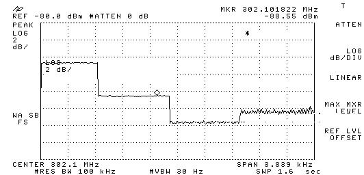
|
Re: HP-8753E Power Cycles at Start Up
Late to the party but just in case it helps someone:
My 8753C which uses the same PSU had a cycling fault. It was caused by shorted diodes on the A15 Pre-reg board. CR6 and CR7.
Cheers, Roger
On Mon, 29 Aug 2022 at 14:22, Ozan < ozan_g@...> wrote: On Sun, Aug 28, 2022 at 06:12 PM, peter bunge wrote:
Can someone tell me how the control loop in the pre-regulator controls the 5vD supply? What I see is T1 connected to line at E1 and E2 and switching FETs that don't seem to control anything and only drive RT1 and RT2.Is there a winding in the loop that acts like a MagAmp? The common connection of the?FETs connects through capacitor?C8 to A15A1 transformer,?what and where is that? .
What am I missing? The manual is very vague simply stating "The?+5D supply is regulated by the control loop in A15"
Am I missing a schematic? I have one for 08753-60215 and one for 08753-60115. there is a T1 on each board which makes it more confusing.
-----
Hi Peter,
I briefly looked at the schematic of 8753A.
Hopefully 8753E is similar. Mains input is rectified on C3 and C4, RT1 and RT2 are inrush current limiting NTCs. Q1 and Q2 turn on alternatively, creating an AC waveform that flows through C6 (probably C8 in your schematic) and primary of "Power Transformer". Return path of the primary is through "T3 Over Current Detection" transformer and back to mains input through S2 switch (which selects 110/220 tap points). 8753A schematic and board layout show the power transformer on A15 board.?
Ozan
|
