
Keyboard Shortcuts
Likes
- HP-Agilent-Keysight-Equipment
- Messages
Search
|
Re: New to the group, troubleshooting HP4261A
Bonjour: See similar on many old HP LCR meters. Do you live in a very clean air location eg countryside or in a big city? Pollution oxidizes contact.
Typical for flaky PCB switch or relay contacts. Heat often affects such flaky contacts. PCB card edge need to be pulled and cleaned off the board, just spraying cleaner everywhere is not enough as contact are oxidized. Bon chance, Jon PS: the tiny bottles of DeOxit are a waste in my experience. High quality PCB cleaner, contact lube, with solvents or alcohol does just as well if not better at 10X lower cost. |
|
Re: HP 8566B repair: -10V rail went down
I believe I located the source of the burn smell. A11A5 L5 and C9 were both charred (see attached image). C9 is a 2.2u 20V axial tantalum. These form a lowpass filter on the -10 V rail for the YTO sampler assembly. I could also clearly make out the smell I'd noticed when I opened this assembly. And, the capacitor in particular smelled really bad. I measured both on my low impedance meter. The cap got a reading of 1.93u (should be 2.2u) and 1.544ohm ESR at 100kHz. The capacitance is pretty close but the ESR seems high to me. Still, surprisingly close for something that looks as bad as it does. I didn't attempt a leakage test, though maybe that would be informative.
The inductor measured 0.267u (should be 1.2u) at 100kHz. My best guess for this drop in value is that the high current fused and thus shorted consecutive loops. Does that seem plausible? I also pulled A11A4C3, which is the same part as A11A5C9, but on the YTO loop phase detector. I measured it to have about 1.5ohm ESR at 100 kHz out of circuit, which seems a bit high to me. Also, C28 is the same exact cap on that assembly and measured a fraction of an ohm in ESR. Matt |
|
Re: New to the group, troubleshooting HP4261A
Is it possible that you have a poor "ground" connection somewhere?
toggle quoted message
Show quoted text
On 2022-01-18 1:39 p.m., GeoVE3GZB wrote:
Here is a video of the malfunction. Typically on first start up in the morning it runs normally and then slowly drifts into this state you see. --
This email has been checked for viruses by AVG. |
|
Re: 8594E input attenuator issue?
The symptoms your unit shows point in fact to the O-ring problem. The rubber becomes hard and brittle over the time. I had a couple of attenuators showing the same an fixed them all with 2x1x0.5mm watch crown O-rings. They come from a 'RUIHUA No.4031' set off eBay (yellow-orange sticker on the box). Works perfectly. Just follow the instructions and be careful what you do.
Chris |
|
Re: 8594E input attenuator issue?
At 08:20 PM 18/01/2022 -0800, you wrote:
The dbm readings are within specs as long as I use a multiple of 20 inThis video? HP RF Attenuators: o-ring repair 'Failed o-rings' means stuck o-rings, that prevent some actuator plungers from moving. Hence wrong attenuations. |
|
8594E input attenuator issue?
Hi! In my quest to repair my SA, I am now facing a potential failed input attenuator.? The dbm readings are within specs as long as I use a multiple of 20 in the attenuator setting. For example, -30,-50 attenuate the signal way more than expected. I read about defective o rings that secure the plugers/pustons to the solenoids. I even watched a video of someone repjacing them. |
|
Re: New to the group, troubleshooting HP4261A
GeoVE3GZB
I tried cold spray and I did clean all of the edge connectors. I also went ahead and refreshed the solder joints on all edge connectors contact points where they are soldered in place.
|
|
Re: New to the group, troubleshooting HP4261A
?This unit is old enough that the card edge connectors may not be gold plated, they may be tinned connectors. If so, cleaning and a very thin coating of De-Oxit would be a very good idea on all of the edge brd. connectors on all of the circuit cards.
Simply pulling and reinserting the cards may cure the problem. Also your failure mode indicates it is failing as it warms up, so cold spray and a hot air source (hair dryer or heat gun) can be your friends in isolating the problem. Don Bitters |
|
Re: HP Diode ID Help
开云体育Hi Tom:I expect that a sorting machine, like that shown on my web page: would be setup to bin the diodes where each bin would be matched to some spec and there would be a number of adjacent bins.? I don't remember how many bins there were but about a dozen. PS Note HP test equipment. 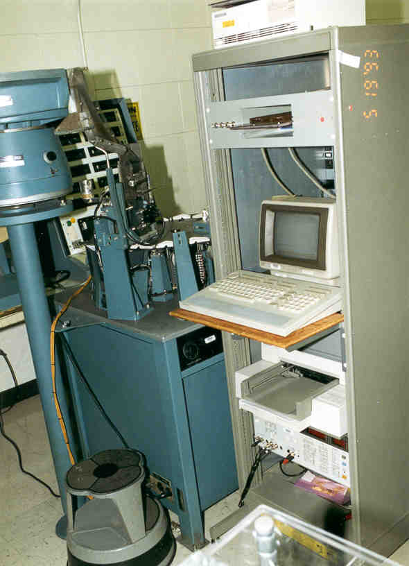
-- Have Fun, Brooke Clarke axioms: 1. The extent to which you can fix or improve something will be limited by how well you understand how it works. 2. Everybody, with no exceptions, holds false beliefs. |
|
Re: HP 8566B repair: -10V rail went down
"Harvey White" <madyn@...> writes:
A good place to check for burned smell would be the RIFA capacitors onI did check these, however, I couldn't discern any smell coming from the RIFA or the input filter, so I think they're probably not the source. I'll probably replace them anyway, given the horror stories I've heard. Though I'm in the US, so doing so is likely a bit less urgent. This reminds me of another question I had recently. I noticed the one standalone RIFA was wrapped in black heat shrink. I don't have the unit open at the moment, but I can send a picture when I open it up again. I haven't seen this before and was wondering why. Is it intended to act as an additional seal against moisture? Back to troubleshooting: although the unit continues to work consistently, the smell reappears every time I turn the unit on. It's strong enough that it concerns me, so I'm thinking of ways to localize it. Some general thoughts: It's not clear whether the fact that the smell occurs when the unit is powered on is because current is burning an already burned part, or if it's existing smell that is now entering the surrounding room because the fans are blowing air into the room. To determine this, I may very temporarily disable the fans. If the smell is occuring because the fans are blowing air, then maybe I don't have an active problem to worry about. On the other hand, if it's not the fans, then I can probably resume the test of pulling the assemblies until the smell goes away. The fact that the smell has probably distributed through the instrument makes it harder to locate. So I may try to blow the smell out of the instrument with compressed air and then try again. I liked Bill's idea of the straw; will give this a go. If my nose fails me, I have a cheap air particulate matter detector that might have better luck. I'll use the straw trick here as well. Other ideas appreciated. Matt |
|
Re: HP Diode ID Help
I came across an old HP price list from 1971 where HP was asking a whopping $8.55 for the 5082-2308 matched pair.? The matched quad was $27.15.? At that time HP was also offering the individual 5082-2303 (1N5157) diode for $3.30. ? While looking around I recently noticed a single diode on ePay offered by a chap in Britain for around $24.00 ? Given the meticulous testing of devices by HP I am sure that they thought of nearly every factor, both electrical and environmental, that would affect the results. ? Greg |
|
Re: HP 8566B repair: -10V rail went down
On Mon, Jan 17, 2022 at 06:07 PM, Matt Huszagh wrote:
Interesting. Why wouldn't the designers use a fuse closer to the max------ I think your question is if -10V is supplying 1.5A from your measurement why a 5A fuse. ?Fuse in -10V section carries current of -5.2V supply in addition to -10V. The fuses are there in case current limit circuit fails, otherwise current limit of each section looks comparable to fuse rating and they will act faster than the fuse. Foldback current limiting is used which reduces current limit when there is a short so the fuse doesn't even see the peak current for long during a short, probably the reason why you were measuring low current out of -10V supply when there was a short, i.e. it was doing its job.? Ozan |
|
Re: HP 8566B repair: -10V rail went down
So many very good responses. The old smoking tantalum cap issue. How many pieces of HP test equipment have I picked up for little cost because of those. I think shorted tantalums are my friend. That said. Often in HP did a very good job in designing the power supplies with protection for over current. Typically you will find a low value resistor in the emitter of the output stage. Across that resistor is the base and emitter of another transistor. To get a rough figure of current, take .6V/the sense resistor. (Caution sometimes its not quite this easy) Another absolutely great failure point is the molex connectors often used for power in the test equipment. My god do those make for great intermittent operation. Look for slightly discolored plastic. I have seen the heat actually causes the PC board connector side to lose it solder. This is actually very hard to repair. As at that point the PC board is actually damaged. So you have to bypass the connector. But usually only 1 or 2 leads, the rest are still good. Also sometimes just cleaning a heated molex connector restores it. Good luck Paul WB8TSL |
|
Re: HP Diode ID Help
Yes, indeed, matching to that level in general requires not insignificant effort, hence the reference to cost. However, if the diodes aren't from a random collection, but rather from the same general region of a wafer, the matching should be pretty good, even for Schottkys. And in the old days, HP made their own Schottkys, so that option would've been readily available to them. I do not know, however, if they took advantage of that option, but if they had to crank out other than a small number of matched quads, I bet they did something like that.
toggle quoted message
Show quoted text
-- Cheers, Tom -- Prof. Thomas H. Lee Allen Ctr., Rm. 205 350 Jane Stanford Way Stanford University Stanford, CA 94305-4070 On 1/18/2022 00:28, Craig Sawyers wrote:
CraigTom, |
|
Re: HP8563E A6 powers supply-What is the maximum current per voltage rail
On Sun, Jan 16, 2022 at 07:29 AM, David wrote:
Hi,---------- Easier to guess for the supplies with IC regulators but a back of the envelope guess: +28V -> 1.5A -12.6 -> 1A +15V -> 3.7A -15V -> 3.1A +5V -> 7.8A -5V -> 1.4A These estimates depend on actual supply voltages, sense resistor value, simplifications, etc. so at best +/- 20% accurate.? If you are seeing very different values I can look at it again.? Ozan |
|
Re: HP Diode ID Help
CraigTom, |

