
Keyboard Shortcuts
ctrl + shift + ? :
Show all keyboard shortcuts
ctrl + g :
Navigate to a group
ctrl + shift + f :
Find
ctrl + / :
Quick actions
esc to dismiss
Likes
Search
Ubitx V6 amp control
|
I was considering an old school method. Since I'm going to go to a desk mic for my uBITX v6, I'm going to put together a relay box activated by a ptt switch. It worked in the old days (1970's), so I don't see why it won't work now.?? On Sat, Aug 21, 2021 at 11:05 AM Mitchel Rought <mitchelrought@...> wrote: I was considering duplicating K3 and tapping into the tx signal, was curious if anyone had used anything else |
|
Just use a transistor to invert the keying voltage. _._ On Sat, Aug 21, 2021 at 9:29 AM Mitchel Rought <mitchelrought@...> wrote: has anyone built an amp control for the V6 where the amp needs a ground to be activated, |
|
I would take the T/R logic level signal from the Nano, invert if required, additional delay if required, opto isolate (so there is no common "ground") |
|
Mitchel,
The article from N6QW does work for SSB mode.? It will not work if you go to CAT or CW modes, as there the PTT source comes from somewhere else.? A solution that takes into account all PTT modes is to pull off of the K1 TX signal and feed that to another relay to trigger your PTT line.? That would send the signal to the amp anytime the uBITX is in transmit mode. Even using K1 as the amp PTT source you could get into issues with timing.? For some situations you need the amp on and stable before sending the RF from the uBITX, in others, you may need to switch the amp input to a 50ohm load before allowing power to the amp.? Each amp would need to be investigated to ensure proper operation.? Most should work with the K1 switching. I have not done this interfacing with the uBITX, though I have with other rigs.? At the time I was playing with the DIY kits from eBay I did not have a clean uBITX that I could feed to an amp.? Take that into account when you make your choices. 73 Evan AC9TU |
|
Mitchel,
That scheme is actually what I was suggesting; using the TX signal to drive another relay like K3.? If you parallel off of the K3 coil then you do not need to add the diode and cap protection.? Note the differences in the ground connections of the relays, the KA to KC relays need both the TX set high and the other coil contact pulled low by the filter selection outputs of the Nano through the transistor drivers.? You DO need a relay to convert the 12volt TX signal to a pull to ground signal. The alternative is to duplicate the Q15 circuit and use the transistor as an open collector pull down.? You also need the diode and capacitor protection for the transistor.? This might be the preferred way if you need the amp switched before the uBITX, as there is no relay delay from K1.? It would drop the PTT sooner than the TX off of the relay K1 approach.? This is why I stated you need to understand the amp requirements.? Most amps and the uBITX should be happy with adding another transistor circuit like Q15 driven off of the T/R signal.? The uBITX should like that as the amp input should be set up before the RF is applied to it.? Depending on the amp, it could cause "clicks" on the output.? The advantage to the uBITX is it would not have a short high SWR while the relays switch the antenna and amp input pads on the amp around. Again, I must stress that I have not done this with a uBITX, so you may want input from others who have done so. 73 Evan AC9TU |
|
Mitchel,
Here is the schematic from HFSignals: 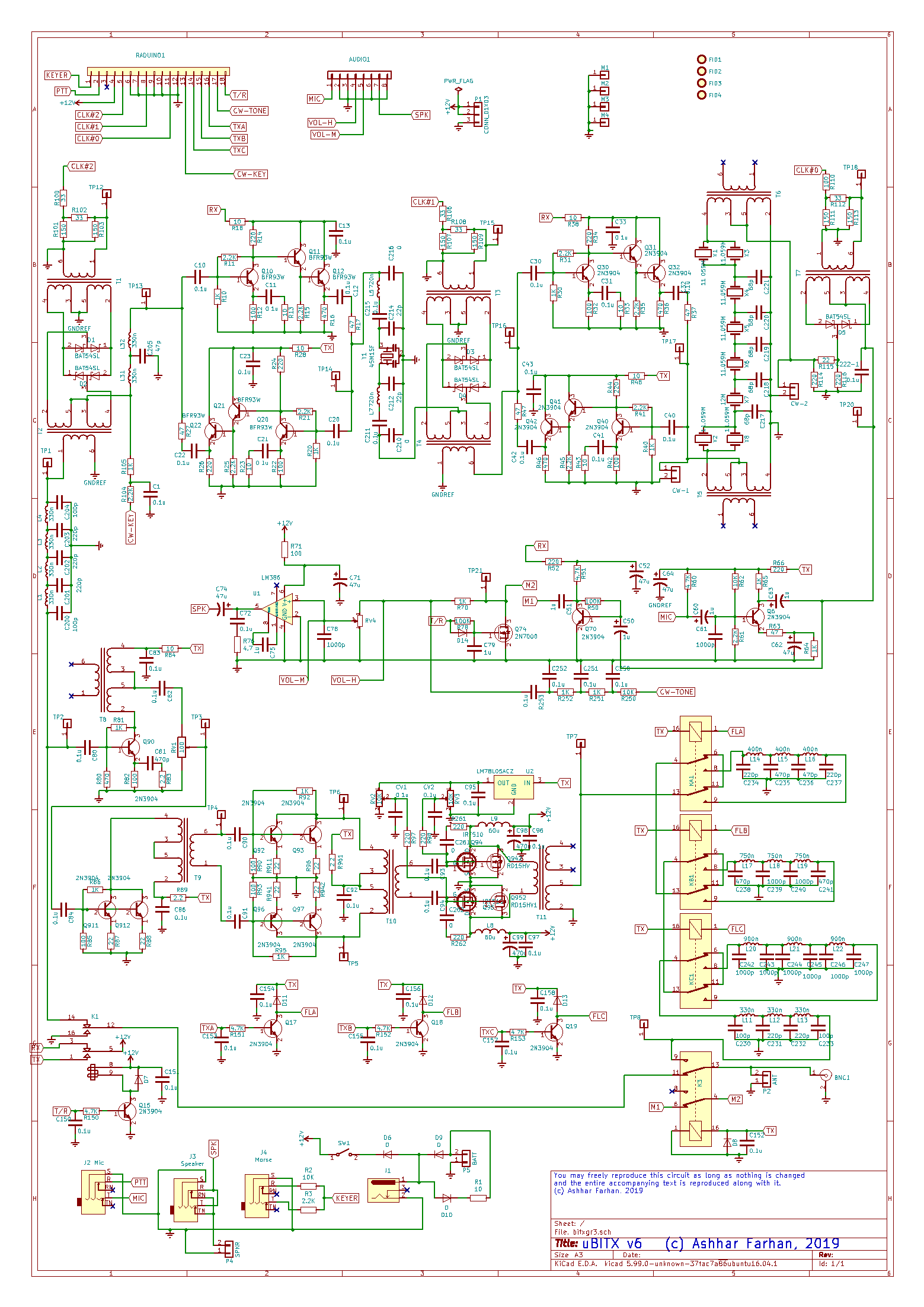 I am talking about duplication of this part of the radio, with the coil of the amp relay in place of? K1 for the new transistor.? You would need to duplicate all of the components and tap into the T/R signal on R150 that feeds Q15 that then drives K1.? The PTT to the amp can be off of pins 1 and 5, or 12 and 16 of the new relay like K!. The alternative is to parallel off of the K3 relay coil and using one of the contacts of the new K2 to trigger the PTT line of the amp. We are really saying the same thing, just getting caught up in the words. 73 Evan AC9TU |
|
Mitchel Rought
Evan
you are exactly right, took a step back so to speak and looked at the big picture and both ideas would solve the problem it's nice to be able bounce ideas around without anyone getting upset maybe the rest of the world could learn a lesson from ham radio operators thank you for your time and knowledge, again you've helped me see through the problem 73 mitch |
to navigate to use esc to dismiss