
Keyboard Shortcuts
Likes
Search
Calibration & filters
#calibration
#filters
|
Good mornning,
As some of you know, I designed and distributed the Raduino32 PCB, which replaces the original version 6 Arduino Nano with an ESP32 microcontroller. ?
The software has been built from the original Raduino, version v6.3.1 available here:?
The software has tried to be true to the original and reproduce the oscillator control as much as possible. However, I still have some doubts about the values of the intermediate frequencies and Oscillators 1, 2 and 3. The following values are defined in the sketch:
In LSB/USB mode the frequency of oscillator 2 (OSC2) is set by adding the values of "firstIF" and "f" (frequency to receive): Referring to the diagram below, suppose we are receiving a USB signal at 10MHz and the spectrum is 10MHZ + 5KHz (Fr). After the first mix, the difference between OSC2 (55005000 Hz) and Fr (10000000-10005000 Hz) will be the first intermediate frequency IF1 (45005000-45000000 Hz) in LSB mode. Here, the first question appears: What is the bandwidth of the 45 MHz filter? Is 45,000,000 Hz the center frequency of the 45 MHz filter passband or is it the lower limit of the passband?
If it is the lower limit everything should be fine but if it is the center frequency, part of the 45 MHz + 5KHz spectrum could be outside the filter passband.
If the received signal were LSB, the spectrum would be 10MHz - 5KHz and the intermediate frequency would be 45005000-45010000, so the 450010KHz - 5KHz spectrum would be even further from the center of the passband. Something similar would happen in relation to the second intermediate frequency and the 11.059 MHz filter. My knowledge of SSB and filters is very limited, so I ask, are my assumptions correct? Am I doing something wrong? Saludos? 搁补尘ó苍 EA4GZI |
|
Hi Ramon,
I am not sure of the following information but will offer it for me to learn as well. 1 - The 3db bandwidth of the 45MHz "roofing filter" is 15kHz, not 5kHz.? I found multiple references in the Groups.io messages that stated this value. 2? - The center frequency of the 4 pole filter (the two in parallel on both the input and the output are for matching and ripple reduction) is lower than the stamped frequency of the crystals.? The center will shift down when building the filter and adding the capacitors.? I believe that it is closer to 11.057MHz.? I do not have the specifics of the crystals used to ensure that actual value.? You can see on this page that the center frequency will go down for the reference 10MHz crystals used: I used approximate values from a Mouser datasheet to plug in the 11.059MHz crystal parameters. 3 - The upper and lower sidebands are swapping positions depending on the stage and the mode selected.? The rule is that the signal being subtracted (the lower frequency) will swap sidebands.? So after the first mixer, the sidebands are swapped and what was the upper sideband is now the lower sideband.? If USB is selected, Osc 1 is subtracted from the input signal, and no swapping occurs.? The OSC1 is raised above the input signal for LSB, and the sidebands are swapped again.? At the DeModulator, the reference OSC 0 is higher than the signal, so swapping occurs.? The frequencies are selected so that the lower sideband is below the passband of the SSB filter, and only the USB comes through regardless of USB or LSB selection. The simple answer to your question "...?are my assumptions correct?? " is no, they are not.? The best proof is that the uBitx does work.? The documentation is simplistic to make it easier to understand, not to use it to redesign without detailed knowledge of how each stage works. As stated in the first sentence, I am not positive that the above information is 100% accurate.? I welcome any corrections or clarifications to help me understand. 73 Evan AC9TU |
|
Hello,
This is a question I ask myself with the KD8CEC software? and how to calibrate well see here: [email protected] | Test after calibration [email protected] | ?talonnage de fréquence accidentellement g?ché [email protected] | Frequency calibration on a lab cdt |
|
Thanks Evan,
Obviously, I didn't intend to question the design, just better understand the operation and settings. I have modified the drawing of the diagram to extend the bandwidth of the filter from 45MHz to 15KHz, although this does not change the essence of my doubts. Referring now to the first intermediate frequency and the first filter of 45 MHz, if we receive a USB signal of 10 MHz, with the value of OSC2=55005000 HZ, we will have a 1st IF in LSB mode of 45005KHz -5KHz.
?
If the center frequency of the filter is 45 MHz, the spectrum of the LSB signal will be above this frequency. (red tracing)
Should we decrease the OSC2 frequency by 2.5 KHz down to 55002500 HZ??so that the LSB spectrum is located in the center of the filter passband? (blue tracing) ?
However, if we change the frequency of OSC2, in LSB mode, the spectrum of the first intermediate frequency would be 55002.5KHz Hz + 5 KHz and it would be further away from the center frequency.
?
Shouldn't the OSC2 frequency be different for USB and LSB modes, so that the spectrum in the 1st IF is always centered in the passband?
?
搁补尘ó苍? EA4GZI |
|
Here's a reasonably concise bit of math showing how the v3 uBitx works. |
|
I previously wrote:
>? To measure the 45mhz filter, sweep CLK2 through 45mhz while simultaneously sweeping CLK1 exactly (11.052-0.002)mhz above CLK2. where (11.052-0.002)mhz = 11.050mhz is my best guess at the center of the second crystal filter, that 0.002mhz is the difference between series resonance and parallel resonance. Should be good enough, we just need to get a measurable sine wave to sneak through. But you could instead use whatever number you measured when sweeping that 11mhz filter in the previous step. Jerry, KE7ER |
|
Shouldn't the OSC2 frequency be different for USB and LSB modes, so that the spectrum in the 1st IF is always centered in the passband?
You could do that but it would be needlessly complicated due to how wide the 45mhz filter is.? If the suppressed carrier of signals received is set in the middle of the passband, you receive LSB off to one side of center and USB off to the other side.?? And so you end up using 6 khz of the filter. These questions got me to thinking about where the center of the filter is, so I wrote a routine ( Teensy audio library version ) to sweep across the filter and measure the noise at different places.? The center of my 45 mhz filter seems to be 45000000.? // a test to find the center of the 45 mhz filter, call once per ms void test_1st_IF(){ static int tm; int32_t off; int i; int mi = 0; float mp = 0.0; float val; static float vals[40]; ???? // run once per second ???? ++tm; ???? if( tm < 1000 ) return; ???? tm = 0; ??? ? ???? peak1.read(); ???? for( i = 0; i < 40; ++i ){ ??????? off = -20000 + 1000 * i; ??????? si5351bx_setfreq(2, vfo_a + IF + off ); ??????? si5351bx_setfreq(1, IF + off - BFO );????? // usb ??????? while( peak1.available() == 0 ); ??????? //Serial.print( i );??? Serial.write( ' ' );? Serial.println( peak1.read() ); ??????? val = peak1.read(); ??????? vals[i] += val; ??????? si5351bx_setfreq(1, IF + off + BFO );????? // lsb ??????? while( peak1.available() == 0 ); ??????? val = peak1.read(); ??????? vals[i] += val;?? ? ???? } ???? for( i = 0; i < 40; ++i ){??????????????????? // find highest, index zero may have some of the normal signal so discard ??????? if( i != 0 && vals[i] > mp ){ ????????? mi = i; ????????? mp = vals[i]; ??????? } ???? } ???? Serial.print( mi ); ???? for( i = mi - 10; i <= mi + 10; ++i ){ ??????? if( i < 0 || i >= 40 ) continue; ??????? Serial.write( ' ' );? Serial.print( vals[i] ); ??????? if( i == mi ) Serial.write('*'); ???? } ???? Serial.println(); } |
|
You could let the signal jump around in the 45mhz filter like that,?
toggle quoted message
Show quoted text
should work ok but USB won't sound quite like LSB. That's exactly the problem that was complained about in this thread: ? ??/g/BITX20/message/44278 The code presented in that post keeps the signal of interest centered in both filters for both USB and LSB. Regarding my scheme to plot curves for the crystal filters: You may have to assert CW_KEY to get enough energy from CLK2 to make it through the 45mhz filter. Could turn on CLK0 (the BFO) and monitor the audio instead of implementing an RF detector. Jerry, KE7ER On Wed, Feb 23, 2022 at 04:12 PM, Ron Carr wrote: Shouldn't the OSC2 frequency be different for USB and LSB modes, so that the spectrum in the 1st IF is always centered in the passband? |
|
Good morning,?
? First of all, many thanks to all of you, Evan, Gerard, Jerry, Ron, for your interest and inputs. There have been a lot of ideas and suggestions and I think that, without wanting to invent the wheel, it would be good to put it all together in one document and try it all out.
?
I put myself to the task of trying to summarize all these things scattered throughout the forum.
?
Unfortunately it will take me a few days to do it but it will be interesting. Please allow me a few days to put all these ideas in order. Saludos 搁补尘ó苍 EA4GZI P.S. Jerry:?second filter crystals in versions 5 and 6 are 11059000 Hz |
|
Jerry,
in the post?? ?/g/BITX20/message/44515 I think you’re answering exactly the question I’ve been asking for some time. The frequency displayed is that of the carrier ( which is deleted, as well as a band according to the choice of USB mode). The frequency actually received is in fact either higher or lower by a few kilohertz compared to this theoretical carrier displayed. (One of the 2 bands to choose from) A mechanism on the frequency calculation of the clock2 (Software) must therefore be done. I think that the question asked thus depends on the expected useful width for the SSB band (so value(s) of clock 2 in USB and LSB mode. The question is therefore whether we use the width of 15khz of the 45MHZ filter and position ourselves either slightly above or below the 45MHZ at the output of the ring modulator. For me, it would be more perfect if the clock 2 would allow to be at the center of this filter, so to have a always a perfect signal of 45mhz on the output of the ring modulator in all cases. but i am an expert, but only some logic we have to see how that is made in the soft (for me KD8CEC) cdt |
|
Gerard,
toggle quoted message
Show quoted text
You're on the right track. The code in this post: ? ??/g/BITX20/message/44278 exactly centers the desired signal in both crystal filters. It assumes that you know the center frequency of both filters. That code assumes that the center of the sideband is 1500 Hz above the suppressed carrier for USB or 1500 Hz below the suppressed carrier for LSB. You can adjust that 1500 Hz offset by changing the value of cbt The radio should work fine once the above 3 parameters are properly selected but the value of ftune may be off a few hundred Hz. The value of ftune (the frequency of the suppressed carrier that the uBitx is tuned to) can be calibrated by adjusting the value of si5351bx_vcoa to accurately reflect the actual frequency of the VCO internal to the si5351, which should be very close to 875mhz and is exactly 35 times the nominally 25mhz si5351 reference oscillator. The code assumes that the BFO is always below the 12 mhz crystal filter, so CLK1 is 12mhz above 45mhz for USB and 12mhz below 45mhz for LSB. This is how the original v3 uBitx firmware was coded. If the BFO is to be above the 12mhz crystal filter, then the code should be adjusted so CLK1 is 12mhz below 45mhz for USB, and 12mhz above 45mhz for LSB. The upper edge of the 12mhz crystal filter passband is sharper than the lower edge, see figure 3 of ? ? Fixing the BFO to always be above the 12mhz crystal filter would give better rejection of the opposite sideband and any residual carrier.? However, on the early uBitx (and Bitx40) rigs with a 12mhz IF,? it was found that harmonics of that 12mhz BFO could beat with harmonics of the 16mhz Nano processor clock to create an audio tone, and that this was more likely to happen with a high side BFO. A rig with an 11.059mhz IF should not have this issue. I have no idea what the various firmware releases are doing now. Jerry, KE7ER On Thu, Feb 24, 2022 at 02:25 AM, Gerard wrote: The question is therefore whether we use the width of 15khz of the 45MHZ filter and position ourselves either slightly above or below the 45MHZ at the output of the ring modulator. |
|
Hi Jerry,
There is something I don't quite understand about this first filter.
?
"Typically, the 45mhz filter seems to be centered around 44.995mhz"
Suppose this is true.
In version 6 firmware, the value of OSC2 is fixed and is equal to 55.005 MHz, so the signal of the 1st IF will be from 45.005 to 45.002 MHz and it would clearly be on the upper falling edge of the filter curve and would still be but what if the center frequency was 45MHz.
What am I doing wrong? 搁补尘ó苍 |
|
Ramon,
toggle quoted message
Show quoted text
I have no idea what the v6 uBitx code does. It may well have the sideband of interest is positioned differently in the passband of the 45mhz filter for USB operation than for LSB. However, the 45mhz filter is likely much wider than you show in your drawing,? the 3dB bandwidth may be greater than 25khz.? The response is flat enough that moving the signal within the passband has not been an issue for most people. Here's a complete C program to test the code that was posted in msg 44278 I have adjusted the numbers so the filters are centered on nice round values of 45mhz (not 44.995mhz) and 12mhz (not 11.998mhz), and the bfo offset is 2khz (not 1.5khz).? This makes the computations easier to follow, though the original numbers are more accurate for the uBitx. // ##############################
#include <stdint.h>
#include <stdio.h>
?
// Initialized to typical values, can be configured by the user
uint32_t? f45c? = 45000000;? ? ?// center of 45mhz filter
uint32_t? f12c? = 12000000;? ? ?// center of 12mhz filter
uint32_t? pbt? ?=? ? ?2000;? ? ?// bfo is 2000 hz below f12c
char? ? ? isUSB = 0;
?
// Compute these values:
uint32_t? bfo, clk1, vfo;
?
// ftune is the freq in hz we want the rig tuned to
void do_tune(uint32_t ftune) {
? bfo = f12c - pbt;
? if (isUSB)? {
? ? // For USB, ftune = vfo-(clk1-bfo)
? ? clk1 = f45c + f12c;
? ? vfo =? ftune + (clk1-bfo);
? } else {
? ? // For LSB, ftune = vfo-(clk1+bfo)
? ? clk1 = f45c - f12c;
? ? vfo =? ftune + (clk1+bfo);
? }
}
?
void main(){
? uint32_t ftune=10000000;? ? ? ?// 10mhz carrier for the incoming signal
?
? isUSB=0;? ? ? ? ? ? ? ? ? ? ? ?// Try first for LSB reception or transmission
? do_tune(ftune);
? printf("isUSB:%d bfo:%d vfo:%d clk1:%d \n", isUSB, bfo, vfo, clk1);
?
? isUSB=1;? ? ? ? ? ? ? ? ? ? ? ?// Now try for USB reception or transmission
? do_tune(ftune);
? printf("isUSB:%d bfo:%d vfo:%d clk1:%d \n", isUSB, bfo, vfo, clk1);
}
// ##############################
The above program prints the following result when compiled with gcc on my linux machine: >? ?isUSB:0 bfo:11998000 vfo:54998000 clk1:33000000?
>? ?isUSB:1 bfo:11998000 vfo:55002000 clk1:57000000?
The first line is for LSB operation (isUSB=0), where the sideband of interest is centered 2khz below the 10mhz carrier, or around 9.998mhz. That 9.998mhz is mixed with a vfo of 54.998mhz, the product has that sideband centered at 45.000mhz This is mixed with clk1 of 33.000mhz, giving a product that is centered on the 12mhz filter. The bfo is set 2khz below that 12mhz product, right where the suppressed carrier would be. Note that the sidebands got inverted since clk1 is 12mhz below the 45mhz IF, as described in post 44515 For the second line, we have a USB signal with the desired sideband centered on 10.002mhz? This gets mixed with a 55.002mhz vfo, giving a product with the desired sideband centered on 45.000mhz The clk1 of 57.000mhz moves that down to be centered on the 12.000mhz filter. Since clk1 is now 12mhz above the 45mhz IF, there is no sideband inversion, and this is USB operation. Jerry, KE7ER On Thu, Feb 24, 2022 at 11:54 AM, <ramonlh@...> wrote:
Hi Jerry, |
|
Ramon may be correct about the 45mhz filter being +/- 7.5khz wide, so a total of 15khz of 3dB bandwidth.
toggle quoted message
Show quoted text
Still, I could imagine a 2khz wide SSB signal sounding good enough when?it jumps around by 3 or 4 khz within that passband when switching between LSB and USB.? Not ideal. Jerry, KE7ER On Wed, Feb 23, 2022 at 03:50 AM, Evan Hand wrote: 1 - The 3db bandwidth of the 45MHz "roofing filter" is 15kHz, not 5kHz.? I found multiple references in the Groups.io messages that stated this value. |
|
I did dig through the N8ME code with the VU3GAO mods and can verify that that version does not adjust the OSC 2 (VFO or CLK#2) based on the sideband.? It uses 45MHz as the default base and then adds the dial display to set the VFO.? The OSC 1 (2nd IF or CLK#1) is set by adding or subtracting the BFO frequency from the 45MHz base.? The BFO is limited to a Max of 11.058MHz and a minimum of 11.048MHz.? This puts the BFO below the center of the SSB filter, so there is not a sideband swap.?
The current superhet scheme means that the HFSignals documentation needs to be updated.? As can be seen on the image capture from the site, the CLK#1 signal is miss labeled.? It should be 57MHz for USB and 33MHz for LSB. 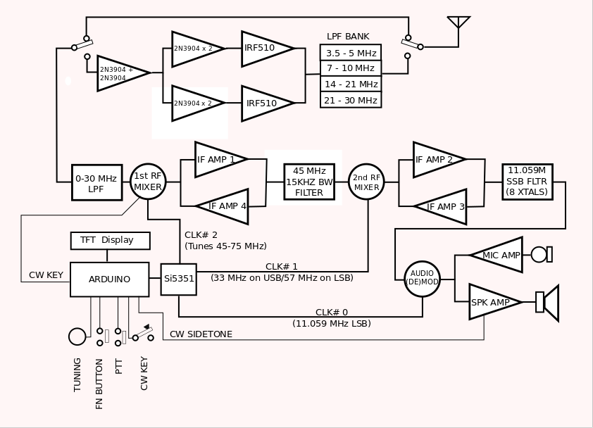 I did verify in the code and measured the actual clock signals on one of my v6 radios. Thank you, Jerry, for providing the information that helps clear up how the software is working. 73 Evan AC9TU |
|
Hola,
This is the 11.059 MHz filter curve of my uBitx v6. Manually measured with a generator injecting the signal at the input point CW1 and measuring the output at CW2 with an Anritsu ML424A. Laborious but effective. The "dbm" values are relative.? It is very similar to what Jerry explained, the bandwidth of 2.75 KHz and the center frequency at 11.057415 MHz. Saludos, 搁补尘ó苍 EA4GZI |
|
Good job on the filter plot!
toggle quoted message
Show quoted text
The crystals coming in from the vendor might have a tolerance of +/- 100ppm,? so might vary a khz or so between 11.058 to 11.060mhz on the parallel resonance. They bin the crystals by frequency when putting these rigs together, make sure each rig gets a matched set within a 100hz or so. Series resonance is about 2khz down from parallel resonance, so I'd expect passband center for different rigs to have a range of roughly 11.056 to 11.058mhz. The BFO needs to be set a couple khz below the center of the filter, this setting will vary from rig to rig. 2dB of ripple is not all that good, but generally good enough. We could automate a procedure using the Arduino's "Serial Plotter" and the Si5351 to show plots quickly, allowing the experimenter to mess with?the capacitors in the filter and the termination impedances till a flat response is achieved. ? ??/g/BITX20/message/32628 ? ??/g/BITX20/message/32630 The fact that most don't really notice 2dB of ripple all that much suggests that? operating near the edges of the 45mhz filter is not too big of a deal. Ramon's plot shows both sides of the filter to be roughly about as steep. I'd expect the high frequency edge to be steeper, see figure 3 here: ?? Jerry, KE7ER On Fri, Feb 25, 2022 at 05:06 AM, <ramonlh@...> wrote:
This is the 11.059 MHz filter curve of my uBitx v6. Manually measured with a generator injecting the signal at the input point CW1 and measuring the output at CW2 with an Anritsu ML424A. Laborious but effective. The "dbm" values are relative.? |
|
Hello,
I think it’s great idea to be able to display the SSB filter response curve with what you call the serial plotter. In fact, it would take at least 2 versions, one for the Nextion screen and one for the standard IL screen Then in this program offer the choice of SSB filter test of 12 or 11 MHZ Indeed, you could "tune" the filter with capacitor ,? a bit like this video Before that save the data with Ubitx manager and then load the PGM, unless all this would be put in the versions (at least 2 Kd8CEC and Ubitx V6) or use a 2nd nano loaded for the test. cdt |
|
My v3 has the standard 16x2 LCD display, same as what shipped with v4 and v5. // Print tick marks on bottom every 10 samples using sample number n in second trace void serial_plot(uint16_t v, uint16_t n) { ? ? uint16_t v2=0; ? ? Serial.print(v); ? ? Serial.print(" "); ? ? if ((n % 10)==0) v2=10; ? ? if ((n % 50)==0) v2=50; ? ? if (n==0) v2=1023;? ? ? ? ? // Establish graph to be 1023 high ? ? Serial.println(v2);? ? ? ? ?// Add tick marks on bottom of graph }
On Fri, Feb 25, 2022 at 07:48 AM, Gerard wrote:
Hello, |
|
Hello,
thanks for the return Indeed, I saw then that the trace is done on the PC. Can you confirm my method from an Arduino nano "new" after connecting it via USB port 1) I launch the Arduino software? ? 2) I copy the program of your post 3)Compile and load it in the nano 4)lauch on software option "Tools", choice serial plotter
5) reset the nano to start
Tell me if this is the right way to go, I can’t do it now because I don’t have a 2nd Nano, but if it can be used for others cdt |