Keyboard Shortcuts
Likes
- BITX20
- Messages
Search
|
Re: UBITX Assemly Wiki Page
#ubitx
MAX
开云体育That’s the best one yet. ? Regards. ? Max K 4 O D S. ? I've Never Lost the Wonder. ? Antique Electronics Site: ? ? From: [email protected] [mailto:[email protected]] On Behalf Of K9HZ
Sent: Sunday, May 13, 2018 10:39 PM To: [email protected] Subject: Re: [BITX20] UBITX Assemly Wiki Page #ubitx ? There is a really trivial solution to this reversing diode-fuse thing.? My drawing is awful but you get the idea…? You just need a 50 cent 10A 12V relay.? ? ? ? Dr. William J. Schmidt - K9HZ J68HZ 8P6HK ZF2HZ PJ4/K9HZ VP5/K9HZ PJ2/K9HZ ? Owner - Operator Big Signal Ranch – K9ZC Staunton, Illinois ? Owner – Operator Villa Grand Piton – J68HZ Soufriere, St. Lucia W.I. Rent it: Like us on Facebook! ? Moderator – North American QRO Group at Groups.IO. ? email:? bill@... ? ? From: [email protected] [mailto:[email protected]] On Behalf Of Jerry Gaffke via Groups.Io ? A search for 'reverse polarity" in this forum shows dozens of hits since the uBitx was released in early Dec.
?
|
||
|
Re: Bitx40 turning clicks
#bitx40
Hi Marco
I just upgraded and Yes that solved most of my problems. Very little clicking and overall better performance.Thank for pointing me inthe right direction Frank |
||
|
Re: UBITX Assemly Wiki Page
#ubitx
W7PEA
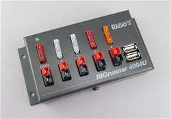
Thanks David, but I'm looking for pics of the Microphone or the Key jack. This is a vanilla install kids. I'll add a note about adding a fuse in the power line. Or yo know it is a wiki... hint hint. I run my power supply into a RIGrunner 4004U.?
|
||
|
Re: UBITX Assemly Wiki Page
#ubitx
THANKS!
Can you please upload a higher resolution version of the diagram? Also the yellow wire is very hard to see against the white backgrond. Perhaps a darker yellow or a light grey background? |
||
|
Re: Should we adopt the KD8CEC firmware?
Ashhar,
I am fully in favor of Dr. Lee's software and developments. When I first got uBitx and fired it up, I was fully disappointed with the poorness of its firmware. Just to mention the stock Split operation. I am sure more fellow users will agree with me. Frankly speaking, it is thanks to CEC software that I decided to keep uBITx and play with it. Memory Manager is a very useful tool, especially if you come to things like the S-meter calibration or the recovery of factory calibration that has been added in version 1.075 I do share some of the concerns of the published responses about the size and perhaps the too many features, but I am convinced about Dr. Lee's ingenuity and I am sure he can come up with a good start up version that can be helpful to beginners and? feature upgradeable. Also if I may suggest, please consider using an I2C LCD that leaves a certain number of ports free for further experimentation and use. The cost of a I2C adapter for the LCD is minimal and I am sure you can purchase the I2C ready LCD cheaper.? A 20 by 4? LCD would make uBITx more attractive marketing-wise. Konstantinos, SV1ONW |
||
|
Re: PA breaking into oscillation? (uBitx)
Update:
Did more experimenting . . . problem goes away when bypassing output filters/relays. Connecting antenna directly to pin 5 of T11 works perfectly - gives me 10W key down?at 7.050mhz, and about 15W PEP at 7.200mhz on SSB. Bobby dazzler! The relays I'm using are branded "HUI KE" HK19F, physically and electrically identical to the VRS2H.?They look kinda beat-up, but appear to be not used. Best thing to do is just replace them . . . they're sealed anyway. I still may?need to re-route my RF out path . . . I'll post another update. -Mike |
||
开云体育You could try forcing the USB chip into the reset state by holding the reset\ line low (FT232RL - pin 19, CP2102 - pin 9). ?Test it out by connecting a 100 ohm resistor from ground to the reset pin. ?The resistor should pull down any pull up resistor but not short out the supply if Vcc is tied directly to the pin. ?it shouldn’t hurt anything to try this but it might keep something from working. Doing this MAY turn off the clock. ?It should certainly reduce noise induced on the power supply lines. If it does work you could add a jumper so you could still use the serial port when needed. Clark Martin KK6ISP
|
||
|
Re: boosting the power on 28 MHz
#ubitx
Is Ashar's mod (post 48199) compatible with Howard's transmitter mod (post 46616)?? Has anyone done both together? -Paul? K9MV |
||
|
Re: Asking for help solving a Hendricks kit BitX20 PA oscillation problem
I am struggling with the PA oscillation issue as well. ? Did you ever solve it?
I did the Martiens mod, (the two resistors, but not the 150 pF capacitor). ?I still get PA oscillation with both the drive level R83 ?and the driver bias R8 set to zero. ? Both IRF510's set to 50ma idle current. ? Everything is good when connected to a dummy load. ?As soon as I connect to an antenna the PA oscillations start-up. An interesting observation, with the transmitter un-keyed and no input signal and with the bias R8 turned all the way down to zero, the driver bias current is not zero. ? I read around 35 mV across the 2.2 ohm source resistor, which calculates out to 16 mA. ? I have set the bias to 44 mV to get 20 mA. ? ?I observe that the drive to the IRF510' is not a symmetrical sine wave. ?One half (positive going) has a small second peak. ?The other half (negative going) looks like a normal sine wave. ? I wonder if I have a bad BS170? |
||
|
Re: UBITX Assemly Wiki Page
#ubitx
开云体育There is a really trivial solution to this reversing diode-fuse thing.? My drawing is awful but you get the idea…? You just need a 50 cent 10A 12V relay.? ? ? ? Dr. William J. Schmidt - K9HZ J68HZ 8P6HK ZF2HZ PJ4/K9HZ VP5/K9HZ PJ2/K9HZ ? Owner - Operator Big Signal Ranch – K9ZC Staunton, Illinois ? Owner – Operator Villa Grand Piton – J68HZ Soufriere, St. Lucia W.I. Rent it: Like us on Facebook! ? Moderator – North American QRO Group at Groups.IO. ? email:? bill@... ? ? From: [email protected] [mailto:[email protected]] On Behalf Of Jerry Gaffke via Groups.Io ? A search for 'reverse polarity" in this forum shows dozens of hits since the uBitx was released in early Dec.
|
||
|
Re: PA breaking into oscillation? (uBitx)
Hello Mike,? For any unstable Finals, you can make it stable in following ways: 1. Add a small value series resistor (approx 12ohm) at the input. And/Or 2. Add Approx 6ohm resistor in parallel with inductor powering Drain of mosfet.? And/Or 3. Tweek the feedback circuit.? I guess for the problem which has begun only because of through hole layout,? The 1 and 2 as mentioned above may give 90% of solution. Regards, Praveen - VU3UJW On Mon, 14 May 2018, 08:35 Mike, <msmith@...> wrote: Thanks for the replies. |
||
|
Re: uBitx Opto Coupler / VFO not working
#ubitx-help
#ubitx
Yep I am using the same manual, on closer inspecttion on the monitor rather then my printout the wire appears to be brown.
So I have everyting wired correctly, now what? |
||
|
Re: PA breaking into oscillation? (uBitx)
Mike:
toggle quoted message
Show quoted text
A layout in through hole, cannot be the same as surface mount, and will have increased capacitance and inductance due to the larger surface area and longer lead lengths that will occur. Howard Quoting Mike <msmith@...>: Thanks for the replies. |
||
|
Re: UBITX Assemly Wiki Page
#ubitx
A search for 'reverse polarity" in this forum shows dozens of hits since the uBitx was released in early Dec.
toggle quoted message
Show quoted text
Here's a few of mine: ??/g/BITX20/message/35353 ??/g/BITX20/message/39877 ??/g/BITX20/message/44499 I've given up trying to right that particular absurdity. Unfortunately, we have hundreds of new hams with no fuse (or too big of one) assuming they are protected when they are not.?? And some of them are bound to be a bit too careless as a result. ? Jerry On Sun, May 13, 2018 at 07:23 pm, ajparent1/KB1GMX wrote:
One small point.? |
||
|
Re: PA breaking into oscillation? (uBitx)
Thanks for the replies.
My layout is?almost identical to the original, except?I'm using all thru-hole components and the Adafruit SI5351. Filters/relays/IRF510's/transformers placement is identical.?Don't have a suitable photo at the moment, not to mention it looks a mess!? And as for Ashhar's comment, everything is very stable otherwise! I've made several FT8 QSO's with 1W output! Actually I stand corrected, the issue doesn't seem to be related to the mixers/modulator. The symptoms on SSB should clear up when I track down the problem on CW. Some sort of ringing effect caused by RF feedback??Can't rule out either?I?may have?some dodgy 510's. For?output transformer T11,?I used the same trifilar format as all the others.?The unused?winding?(4 and 3)?is simply not connected to anything, as per schematic. An earlier post by Ashhar for his prototype stated "8T:10T" for T11. Not sure if this means conventional wound with 8 turns for one (primary/secondary) winding, 10 turns for the other. So maybe a clarification would help. Thanks, Mike |
||
|
Re: VFO / Opto coupler not working
#bitx20
#ubitx-help
开云体育The written description is correct the black wire is pin8 of the Raduino to A on the encoder and the brown wire of pin7 is connected to B on the encoder. The purple wire from pin1 of the Raduino is not used, if you have connected it to the encoder swap it with the brown wire and you should be fine.Skip Davis, NC9O? On May 13, 2018, at 22:13, kj6etl <pa1zz@...> wrote:
|
||
|
Re: uBitx Opto Coupler / VFO not working
#ubitx-help
#ubitx
What manual are you looking at?
toggle quoted message
Show quoted text
Here's the wire-up instructions on the hfsignals website that should be used if you still have the stock firmware that the uBitx is shipped with: ? ?? They show the black and brown wires of digital connector at the top of the raduino going to the? two side pins of the mechanical rotary encoder, the middle pin is ground and so? should get the yellow wire from that same connector.?? If you try it and it works backwords, just swap the black and brown wires at the encoder There are also the two switch pins on the other side of the encoder, one of these gets a ground from that yellow wire, the other is the red wire from that same Raduino connector On Sun, May 13, 2018 at 07:32 pm, kj6etl wrote: oday I completed the build of my uBitx. |
||
|
uBitx Opto Coupler / VFO not working
#ubitx-help
#ubitx
Today I completed the build of my uBitx.
Unfortunately the Opto coupler / VFO is unresponstive. No matter what I do it stuck at LSB A : 7150.00 I tried to push the the reset button on the small board behind the display to no avail. On closer inspection of the manual I noticed a discrepency between the text and the picture. The text tells that the brown wire has to be connected to the Pin B of the opto coupler while the picture shows a purple wire. Earlier in the manual it states that the purple wire from the Raduino board is redundant so I removed it... Looking forward to your input! |