
Keyboard Shortcuts
Likes
- BITX20
- Messages
Search
|
Re: Harmonic performance - SSB vs CW
Warren Allgyer
The signal at TP1, the output of the first mixer is a pure square wave as it is derived directly from the Si5351 in CW mode. The signal in SSB mode is much closer to a sine wave as it is a mix of the Si5351 square wave and the 45 MHz drive that has been filtered by the roofing filter of Y1 and associated components.? The obvious way to fix this is to do the CW generation prior to the roofing filter. What is not obvious to me is the best way to do that. As it stands it is pretty messy. |
|
Re: End Fed antennas w/ uBITX
#ubitx
On Tue, Jul 31, 2018 at 06:38 AM, Warren Allgyer wrote:
In actual operation these losses would be the best case and would be experienced only when the antenna is a resonant multiple of a half wave. The losses when not terminated in a 2470 ohm resistive load, which would be the case if the antenna were used on any band other than the single resonant band, are far higher. On the order of 8 - 10 dB.Thank you Warren.? Your VNA and 'scope plots illustrate very clearly why in antenna literature, "all band" doesn't mean what most folks would have it mean - it almost always means "lossy".? Even commercial manufacturers have a difficult time producing a high transformation-ratio UNUN that operates across multiple octaves of frequency with acceptable losses - it's just not an easy set of design objectives to satisfy...? so for casual construction projects it a reasonable design constraint to limit (focus) yourself to making a transformer with minimal losses across ONE octave of frequency.? I.E 1.8~3.6Mhz; 6~12Mhz, and 14~28Mhz.? Even minimizing losses in the 14~28Mhz range can be challenging, due to the very high transformation ratio (1:49) - look very closely at your use case before choosing core materials - Material #43 isn't? "the best" choice in many cases; in fact I try to avoid it whenever possible below 5Mhz and above 20Mhz because of it's high(er) losses.? Material #61 yields lower losses than #43 for nearly every application in the 10~30Mhz; and Material #31 has lower losses than #43 in most applications at or below 5Mhz.? In practical applications, the loss curves of materials #43 and #31 'cross each other' in the ~8Mhz range, so an UNUN | BALUN made for use on 40 Meters can utilize either core material and achieve a respectable loss figure, when all other design limitations are observed. This is why I strongly recommend designing and building separate matching units for (80)/40/30 meters, and 20/17/15 meters - that way, each can be optimized for minimum losses in the specific band(s) it will be used on. I would use matching techniques for 12/10/6 Meters which don't employ ferites or iron powdered toroids at all.? Air core coils and/or transmission-line sections are compact enough on these bands; yield very generous matched bandwidth figures; and have much lower losses when compared to the toroidal transformers [tuned and un-tuned] being discussed throughout this thread. Cheers, Chuck |
|
Re: ubitx CW straight key wiring
Wow.? I missed that completely by using the front panel PCB that came with the enclosure from . Seems like with online resources like that, the schematic and wire-up page could get updated. Just sayin'... 73, -- Dave, N8SBE
|
|
Re: experience with Sunil VU3SUA's enclosures
#ubitx
I found out that the MH3 mike that came with my KX2 works peachy plugged into the 3.5mm PTT/MIC jack.? No wiring, no fuss.? The up/down buttons, of course, don't work (they cause PTT), but otherwise, I won't have to come up with an adapter for anything. So far, using my Picokeyer plugged in to the CW jack, and my Bulldog paddle for CW.? Works peachy, too. Showed it off at the Detroit Maker Faire (special event station N8M) this past weekend, and it drew a lot of positive comments and questions.? Mine is dark green, and the green LCD sets it off nicely.? Left the lid off so everyone could see how it went together. I'll be at the MI QRP club picnic this Saturday (1000 to 1400 ET), and running CW/SSB on likely 40 and 20 meters, using my Super Antenna on the picnic table with tuned counterpoise wires. 73, -- Dave, N8SBE
|
|
Re: click fix and squeal on transmit
#ubitx
Thanks, Don! In a surprise move, the problem turned out to be uncarefulness on my part. My confidence was misplaced, since I'd used wrong capacitors in a total of four places: both caps in the circuit were 10μf, not 10 nf, and my replacements for C50 and C63 were not polarized. Now that I've replaced all four with the correct caps, the squeal is gone. The click is still audible in the headphones when the volume pot is turned way up, but it's much less than before. I think I'm going to declare this a qualified success and put the radio back in its enclosure.
|
|
Re: Off Topic: Gap Antennas
Vince Vielhaber
If you can, put in 8.8.8.8 for your first name server and see if that does it. That's google's name server.
toggle quoted message
Show quoted text
Vince - K8ZW. On 08/02/2018 04:02 AM, DaveC wrote:
Thanks guys, Don't think it has anything to do with the EU privacy --
Michigan VHF Corp. |
|
Re: ?B FT8 Success!
I went a slightly different direction and picked up a cheap temp fan relay from Amazon:
I superglued the probe to one of the finals heatsink and then played with ON temp and hysteresis temp, I settled on 50deg ON and 35deg OFF.? It was $5 for the fan relay + probe and ~$8 for a 12v 2wire fan.? Works great. 73 Rob de AG5OV |
|
Re: click fix and squeal on transmit
#ubitx
When the rig is not powered or in the receive mode there should be continuity from the Rx connection point to 12V. through relay K1 contacts 3 and 5. That is normal. The squeal is not!
First step in diagnosis is to check the voltage on the gate of Q3 when in transmit mode. It should be below 1 volt referenced to the ground connection on that board. If not, check to see that the ground connection there has the same potential as the ground plane of the BITX. Then track down the voltage discrepancy. The operation depends on Q3, acting as a gate, being turned off, thus opening that gate. If that gate is allowing the I/O (when in transmit, it is the microphone pre-amp output) to be leaking into the audio output then you will get enough feedback to oscillate. If the gate of Q3 is below 1 volt referenced to the source during transmit then Q3 may be bad. If there is voltage on the source, check your solder connections of R4. Keep us informed, please. 73, -Don |
|
Re: Ubitx will be here tomorrow. Any suggestions for a Bitx newbie
#ubitx
Hi there..
toggle quoted message
Show quoted text
do step 3 before step 2. Install that resistor first. Then apply power. 4. The software is already 'loaded'. After you install in a case you will have left me behind. I am not interested in touch screens, etc. Enjoy your new radio:) 73, Bill KU8H On 08/02/2018 01:38 PM, Truffies wrote:
I just received my ubitx building this weekend on cardboard to see if works. --
bark less - wag more |
|
Re: Harmonic performance - SSB vs CW
Warren Allgyer
Allison
I will try lowering the drive to see if it corrects the problem but I am skeptical. I first noted the problem when probing TP1 with the PA unpowered. The discrepancy is already visible at that point. It is pretty clear the harmonics are being generated at the unbalanced mixer. WA8TOD |
|
Re: Ubitx will be here tomorrow. Any suggestions for a Bitx newbie
#ubitx
I just received my ubitx building this weekend on cardboard to see if works. Questions on steps 1. build on cardboard 2. power 3 place 4.7k in key jack 4? ? do you need? to load software? 5. Final listern test to see bands turning rec. 6. Test in dumb load transmit 7. OK build into a case 8. now ready to modify - AGC 9. LCD touch screen add software first to use screen? ? (load hex and how to do in steps please where to find)? dumb all new to me -----Original Message----- |
|
Re: Ubitx will be here tomorrow. Any suggestions for a Bitx newbie
#ubitx
ITs been said but I will repeat.
Build it first and test.? Insure you have the 4.7K in place on the key jack.? Double check wiring. If you are bench testing before boxing it.? Use care to avoid accidental shorts or wires touching the wrong thing and outside events like ESD (carpet static!).? One example seen was taped to a piece of card board to keep everything from moving around, worked well too. Use 13.8 volts for testing as its likely a V4 board (discrete transistor audio amp). If all goes well you may want mods and to pick out what your box is to look like. Good luck! Allison |
|
Re: Harmonic performance - SSB vs CW
Warren,
During my sessions testing the amp it was noticed but the 20Mhz and up spur was higher? on the priority list. Another thing I ran into with a friend was defective low pass filters.? The toroids had different? numbers of turns from other units.?? First try lowering the drive (RV1) and look again.? If it drops its the amp flat topping (overdrive) (can be any stage in the amp up to including the finals.).? That can be voltage starving (less than? 12V at the board) or other problem unnoticed. It is possible that the first amp Q90 is being over driven as well and reducing RV1 will not help then. Generally the CW drive was found to be higher than clean levels of SSB drive so it could? be amp overdrive.? Lowering the DC bias to the mixer during CW TX can help that.? The Mixer (DBM) is?being used as a switch but they can also be used as a variable attenuator as well.? R114 is the?point of adjustment.? Non linear action by the diodes is not an issue as the driving waveform?is square to start with which is why the odd harmonics are stronger on the display.? Add to?that the push pull amps (driver and final) are balanced so the second and forth are better?suppressed but 3 and fifth tend to be the push pull amps weak spot. Also sweep the 3-5mhz filter to insure its working as expected.? Easy to do with power off and tracking generator?as its then isolated.? Also make sure the correct filter is being selected, TX-A/B/C should?all be selected (relay active). If the TX amp is at or near compression try turning up the DC power a Volt or so (caution TA2822!). If the TA2822 is on separate regulated power its safe to go far higher than 13V. Test first as there are many possible solutions depending on the problem. Allison |
|
Re: Harmonic performance - SSB vs CW
That's an interesting finding, and seems quite likely correct.
toggle quoted message
Show quoted text
Thanks for looking into that. One possible solution would be to unbalance either the modulator (as done on the Bitx40 by Allard's mods)? or the second mixer at D3,D4.? In either case, those harmonics should be stripped out by the 45mhz filter (also the 12mhz filter, in the case of unbalancing the modulator).? Would require minor hacks to the firmware to set up the si5351 correctly for CW transmissions after this mod. Jerry, KE7ER On Thu, Aug 2, 2018 at 09:26 AM, Warren Allgyer wrote:
|
|
Harmonic performance - SSB vs CW
Warren Allgyer
I am noting a significant difference in the harmonic suppression in SSB mode versus CW mode.? The two signals are generated in a very different way. SSB is generated at 45 MHz and mixed down to the final transmit frequency by combining with the first oscillator in the balanced first mixer to make the SSB transmission. In CW the 45 MHz path is disabled and the first oscillator is simply moved to the transmit frequency. The first mixer is unbalanced with a DC bias to allow the first oscillator signal to leak through. It appears the act of unbalancing this mixer produces harmonics, particularly high order odd harmonics that are clearly in excess of the -43 dBc requirement. The screenshot shows? the harmonics of an 80 meter transmission at 10 watts. The purple trace is the CW and the blue trace is SSB. Signal source for SSB is a approximately -40 dBV 1 KHz tone with the level adjusted to match the CW carrier level. The SSB signal harmonic suppression is just adequate (green display line) however the CW signal is clearly non-compliant. I am not sure what to do about it yet but wanted to raise the point. I have done a search on this board since I am new and I do not find this has been reported before..... perhaps I missed it? |
|
click fix and squeal on transmit
#ubitx
Hi -- I have had my v3 ubitx working fine, and thought I would install the T/R click fix version 2 from . I'm fairly confident in the circuit I assembled, slightly less confident in the jumpers, trace-cutting, and attachment to the board. The click is still audible in the relay but not in headphones on either transition, and I get a loud squeal on transmit into a dummy load when the volume pot is more than slightly turned up. What should I be looking at to diagnose this?
I noticed continuity between the 12v line and the point marked Rx connection in this section after cutting the trace, which seemed odd: 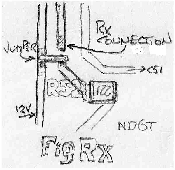 |