
Keyboard Shortcuts
ctrl + shift + ? :
Show all keyboard shortcuts
ctrl + g :
Navigate to a group
ctrl + shift + f :
Find
ctrl + / :
Quick actions
esc to dismiss
Likes
- BITX20
- Messages
Search
|
Re: Alternative Calibration Procedure uBITx v6
开云体育I’ve used that method also, that works too. ? It also takes the advantage of taking the measurement down to audio frequencies. ?On Nov 20, 2020, at 15:23, AndyH <awhecker@...> wrote:
|
|
Re: Alternative Calibration Procedure uBITx v6
I like it!? Simpler than the method I've been using!
toggle quoted message
Show quoted text
I tune to WWV, then hit the WWV Wikipedia page to see what frequency audio tone is broadcast that minute.? I use the WSJT-X waterfall to track the audio tone. 73, Andy On Wed, Nov 18, 2020 at 09:12 PM, Mark Erbaugh wrote:
Following the calibration procedure for my v6, I had trouble zero beating a carrier, so I tried a modified approach that seems to work better for me. With the radio in LSB mode, I tuned 1 kHz above WWV at 5 MHz. WWV's carrier thus creates a 1 kHz tone. I used a program with an audio waterfall (I used FLDIGI) and adjusted the uBITx's tuning calibration until the tone was at 1 kHz. |
|
Re: SWR meter with second arduino
Gerard,
I am not familiar with the multi-display modes.? I would assume that each has an I2C address that is configured as part of the Nextion programming.? This is guesswork on my part. I would assume that the size of the screen does not matter other than the .tft or .hmi file that is needed to program it.? I am sure that there is only one version of the Nano code to work with the multiple Nextion displays. 73 Evan AC9TU |
|
Re: SWR meter with second arduino
Evan,
OK Look here, i like colors on the second Nextion An other tft file? My idea is to have main screen on a future 5" nextion, and use the actual 3.2" to sea swr or scan?. Don't know if possible? I was able to sell electronic components on E.. Y to buy the future 5". Lol. I also receive an Automatic antenna tuner in kit of Ukraine (Less 15 days). Model of N7DDC. (Also wiyh my E..Y solds to pay it.!! There is also a small screen. So, some work to do cdt |
|
WARNING: Promotional offer
Jack, W8TEE
All: I feel badly about the font size error that occurred in my Beginning C for Microcontrollers book, especially since you bought the printed book before it was hardly even reviewed. As it turns out, this error was totally my fault and not KDP's. The new book has increased the font size from 8 to 12-point and I have also added an index, which makes it more usable as a reference. As a result, the page count has increased from 380 to 475 pages. The narrative is virtually unchanged, except for the addition of the index. I wrote to KDP to see if I could get the mailing addresses of the people who bought the book. For reasons I can understand, that request was denied. So, here's the deal: 1. Rip off the front cover of the book and three pages from somewhere near the middle of the book. 2. Mail the pages and cover with a check for $10 (or you can use my PayPal account--email me privately) to me at my address as given in QRZ.com. Be sure to include your address where the new book should be sent. In return, I will mail you a new book to replace the one you just destroyed. I need you to post mark your return pages on or before Dec 5, 2020. The offer dies at midnight on Dec. 5th, 2020. On Dec. 6, I will order enough books to replace those who have ordered new ones. It seems to take Amazon about 14 days to get the books to me. Add in the Holiday mail rush, and it may take a little longer. After they arrive, I will try to mail the new book to you as quickly as I can. It's an imperfect solution to a nettlesome problem, but the best I can come up with. For those who think I'm doing this to make money, I can assure you that, by the time I pay my cost for printing the new book (which increased by more than 20%) and the cost to mail it back to you, I will be losing money on the deal. Still, it's the right thing to do. I do appreciate your support. Jack, W8TEE P.S., Read the three pages from the center of the book before you mail them back! -- Jack, W8TEE |
|
SWR meter with second arduino
Hello,
I was looking at this documentation for my information and I have a doubt about the connection. Look at the comments.. So my question is, what’s the right connection? On the original arduino (the one I call the master) or on the 2nd (the one I call the slave)? Some body have build it? Second question, it seemed to me to have seen that we could connect a 2nd Nextion with this second nano. (Example to display the swr only) I can’t find this doc, unless I’ve revered? cdt |
|
Re: Alternative Calibration Procedure uBITx v6
Hello,
If you inject a signal of 15mhz near the antenna by radiation (Mid 0 to 30MHZ) and watch the beat up to 0 at the oscilloscope just before the SSB filter (or After the 45mhz filter), you must be well calibrated too. I did it like that.?After that, we have to calibrate the BFO. Is that a good method for you? For me, it's work fine cdt |
|
This goes back to the early days of electricity in the mid 19th C, well before
toggle quoted message
Show quoted text
J J Thomson discovered the electron. (Not sure which one of the million trillions he found! :-) ) It was not then known exactly what was a flow of electricity and it was thought to be a stream of some sort. Now, I'm not a student of the Classics, and it is 53 years since I did Latin at school, but I believe that Rheus was Ancient Greek for a stream, so Rheostat is a stream controller in much the same way that Thermostat is a temperature controller. Also from that same period of time, a Rheofore is a length of wire! 73 de Gareth G4SDW On Fri, Nov 20, 2020 at 11:38 AM, Bob Lunsford wrote:
|
|
Re: S-Meter Nextion, ask
On Mon, Nov 16, 2020 at 01:17 PM, lu7yw wrote:
https://www.youtube.com/watch?v=uvukDHvMoXEThere is not enough information here to give any answers. It may help if you details of exactly which UBITx board, which s-meter solution , and which firmware, you are using. Include versions of software.? The more details the better. ? -- Dennis WC8C |
|
Hi,
toggle quoted message
Show quoted text
Until I see an individual schematic I guess that "P1" is "plug number one". Maybe that is my grey hair (or what is left of it). Schematics that I have would label that "VR1". If you happen to see that on a schematic, now you know what it is. 73, Bill KU8H bark less - wag more On 11/20/20 3:24 AM, Raj vu2zap wrote:
A variable pot is shown with an arrow. A pot that is adjusted once and set |
|
Re: RSGB review of the ubitx
I couldn't figure out the IR2028. The pdf refers to annexure A that refers to five other docments with annxures A to N that it turn... If someone could just quote the figure, we would be a happier world. On Fri 20 Nov, 2020, 6:45 PM Harry, G7KNK, <harry.g7knk@...> wrote: An excellent review.? Does anyone know if this kit conforms to IR2028 spec. needed for equipment used by UK Foundation Licence holders? |
|
RES: [BITX20] #For Sale A Few QRP Goodies
#for
开云体育Puxa, legal encontrar radioamadores que também falam o 笔辞谤迟耻驳耻ê蝉! Assim que terminar minhas antenas de apartamento montarei o uBIT 6.1. Grande 73. ? Wow, nice to find radio amateurs who also speak Portuguese! As soon as I finish my apartment antennas I will set up my uBIT 6.1. Large 73. ? Fred Guizini PY2-UBB S?o Paulo - Brazil ? Enviado do para Windows 10 ? De: Bob Lunsford via groups.io ? Tambem falo portugues. Era liinguist em ASA. ? Bob — KK5R ? On Wednesday, November 18, 2020, 3:15:15 PM EST, N8DAH <dherron@...> wrote: ? ? Rubens, Simplesmente n?o tenho tempo para brincar com tudo como pensei que faria. Também estou reduzindo um pouco o barraco e adoro construir coisas.73 ?N8DAH ? |
|
A settable resistor with two terminals is usually called a rheostat.
On Friday, November 20, 2020, 3:45:33 AM EST, Raj vu2zap <rajendrakumargg@...> wrote:
A variable pot is shown with an arrow. A pot that is adjusted once and
set is called a preset and is shown with a short line instead of arrow. 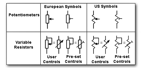 ?
?At 20/11/2020, you wrote: "what component is P1" ????? |
|
Is there a link to the "led/ldr combo" circuit? I get the concept but love shortcuts to their use with a diagram showing components and their values. Bob — KK5R
On Friday, November 20, 2020, 3:43:52 AM EST, SIMON ROSS via groups.io <simonr5@...> wrote:
Vk3ye demonstrates the circuit for the led/ldr combo. I’ve built it and it works to cut high audio peaks? On 19 Nov 2020, at 00:38, iz oos <and2oosiz2@...> wrote:
|
|
Very good information. Very often different words are used where the word is a noun or an adjective when dealing with the same thing. Difference between a Title and a Description. An amplifier "ceiling effect" would seem logical where the gain is at a set level and it's low enough to control the "loud mouths" on the bands but yet will not impede the lower level signals. No doubt it should be in the IF area and this has been the tradition going back to days of the tube radios. A simple diode was added to the first audio amplifier that formed a power supply that fed back to the IF amplifier/s and controlled their gain. It rectified the carrier at this point and formed a DC signal that corresponded to the station you listened to so the audio output was consistent for most all stations. However, this was simple compared to the hoops you have to jump through when not dealing merely with an AM signal; SSB and other modes are much more challenging to have such a circuit. One designer used what is termed an "audio derived" S-Meter circuit that "might" be adaptable to assist in the AGC feature but still may not be transparent to the user. A simple RF gain may not serve the purpose since the user may still be constantly using it to control the High vs Low signals heard, for example, in a net. But you'd in effect be using the audio gain and the RF gain together much like the old regenerative control was used along with the tuning control. Good discussion. Thanks Farhan for this. Bob — KK5R
On Friday, November 20, 2020, 2:44:26 AM EST, Ashhar Farhan <farhanbox@...> wrote:
AGC is a feature and attenuation is a function. Automatic Gain control can work using an electronically controlled attenuation in the signal chain or by using variable gain amplifiers somewhere in the chain. the golden rule of good signal processing is to control the gain as early in the signal chain as is possible. The best gain control is to put variable resistor right at the antenna terminal. The reason is very simple: the amplifiers down the chain have to handle weaker signals and weaker signals mean better fidelity. An audio AGC in a conventional superhet where most of the gain is in the IF stage will overload even on a moderate signals due to the distortions in IF amplifiers. Picture this, there is the lowest level signal that the receiver can resolve, this is set by the bandwidth and the noise figure of the receiver. The? highest signal that the receiver can resolve without distorting is determined by the IIP3 and the phase noise of the local oscillator. The range of signals between the minimum discernable signal and the loudest signal that the receiver can handle without noticeable distortion is your dynamic range. Now, consider what happens if you switch on a 10 db attenuator between the antenna and the receiver. the MDS (minimum discernable signal) has to be 10 times more powerful and on the other hand, the signal level at which the distortion starts to show is also up by 10 db. In effect, to borrrow?Rob, NC0B's words, the dynamic range is a moveable window that can be shifted up or down with attenuators. Most receivers are too sensitive for HF bands. For instance, the ubitx is too sensitive for 40 meters, the atmospheric noise is 100 times more powerful than the internal noise (noise floor) of the receiver. This is wasted dynamic range. if we had thrown in a 20 db attenuator, we would hear exactly the same signals as before but our dynamic range would have been 100 times more. Dynamic range doesn't only apply when you are contesting or having a neighbour who transmits 1000 watts, it is a measure of how sweet the receiver sound is as well. So, why is ubitx so needlessly sensitive? That is, because it is meant to work from 10 meters to 80 Meters. That sensitivity will be needed when the 15 meter opens up in a few years from now. RF attenuation does remain the best place to control the gain, even for an AGC system. The challenge is to build a smoothly varying attenuator that doesn't need any active devices. Active devices in wide open receivers like the ubitx can severally compromise the receiver performance.? I am planning to do a video to explain who careful gain distribution is the key to a good radio design. - f On Fri, Nov 20, 2020 at 9:38 AM TD <dlee@...> wrote: > "what component is P1" ????? |
|
SIMON ROSS
开云体育I used a simple circuit using a ldr and an led to attenuate the loud audio and also connected a meter. It works well. Vk3ye shows it on YouTube?On 19 Nov 2020, at 08:55, Bob Lunsford via groups.io <nocrud222@...> wrote:
|
|
Nice discussion all around. The gain in the ubitx is nicely arranged.
Usually the RF attenuator function in the most sophisticated HF receivers is a maual conrol. Since the ubitx does not use a presmp, I don't require an RF attenuation control. A radio operator csn adjust also the audio gain. But a little AGC can help here. The LED/LDR circuit appears to act slightly logarithmic which is useful. It works pleasantly with the ubitx gain distribution.? A lossy attenuator network at the front of the ubitx would be a bad thing at high part of HF. An experimentor should evaluate sensitivity on 28 Mhz with and without it. Meanehile, leave it out if you don't need it.? 73 curt |
|
Re: Alternative Calibration Procedure uBITx v6
开云体育This is a simple & free method because almost all digital receiving software (FLDGI, etc) accurately measure the audio freq beat tone far in excess of your needs. ?On Nov 19, 2020, at 17:35, iz oos <and2oosiz2@...> wrote:
|


to navigate to use esc to dismiss