Keyboard Shortcuts
ctrl + shift + ? :
Show all keyboard shortcuts
ctrl + g :
Navigate to a group
ctrl + shift + f :
Find
ctrl + / :
Quick actions
esc to dismiss
Likes
Search
T match
|
Hi Paul,
The ATU-100 uses an L-Match tuner with a series inductor ¡°L¡± and parallel capacitor ¡°C¡±. The capacitor is connected to either the input side (TX) or the output side (ANT).
A simple representative circuit is shown below.
The position of the ¡°L¡± and ¡°C¡± on the display indicates which side the capacitor is connected.
If the ¡°C¡± is on top of the ¡°L¡±, the capacitor is connected on the input side (TX).
If the ¡°C¡± is on the bottom of the ¡°L¡±, the capacitor is connected on the output side (ANT).
For information, I have added connections for the additional button and output pins, although it is a bit fiddly connecting to the small via hole pads.
RB1 Input Auto (Step Down) Active Low
RB2 Input Bypass (Step Up) Active Low
RA6 Output INV(TX_REQ) Active Low
RA7 Output TX_REQ Active High
?
The test mode which can be entered by holding the ¡°Auto¡± and ¡°Bypass¡± buttons whilst powering on is quite useful for experimental purposes, allowing manual selection of the L and C values and the position of the capacitor connection.
?
I wound the Stockton bridge for a 5:1 ratio, which is slightly better for QRP, but reduces the maximum power to approximately 40W before overloading the PIC ADC input.
73, Dave ?
|
|
Be careful if you want to use a T-network in an auto tuner. The unloaded Q must be very high, the Q of the T-network loaded by the antenna, on the other hand, very low, otherwise losses due to circulating currents will increase rapidly. This is why I personally prefer the L-network.
toggle quoted message
Show quoted text
73, Martin, OK1RR Dne 11. 03. 23 v 11:22 paul larner napsal(a): Hi all,i asume the atu is a tmatch?,with a manual T type tunner there are two combinations that can match but only one is right,is it the same with the atu-100,if so how does it know what combo is the right one?,or have i got it wrong?.73 |
|
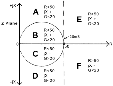
Very well noted! Actually selection of tuner architecture should lie in the character of the load itself. Sometimes specific loads will cause much losses in T-networks, and some will not be tunable at all with L-networks, requiring massive amounts of capacitance/inductance to transform the impedance successfully back to 50+j0 ohm. This means, that one has to define where in the impedance plane the load lies, and then use the appropriate network to get it home. And this cannot be done using just an reflection bridge and calculating SWR. It actually means absolutely nothing impedance-wise, but it's simple and cheap to measure, so we use it. Ideally one would have 3 detectors - resistance, phase and conductance, so the choice of network topology can be clear and unambiguous - and with the lowest losses for each part of the impedance plane.?
There is a very good set of articles by David Knight about this -?  Going back to the ATU-XXXX series of ... well ATU's... they use only SWR for matching, and while this is acceptable for L-networks, having only one optimal solution for each load transformation, consisting of a single set of L and C values, T-networks have one solution with highest Q and lowest losses, and possibly 5-6 other solutions, which will also transform the impedance to 50+j0, but will waste our precious power as heat up to 60-70% in some cases. One other topology, that has only one optimal solution, that can be detected with just an SWR meter is the Differential-T network, where you have handicapped the T-network, by tying together the two capacitors in one differential (butterfly) variable capacitor. This robes one of the degrees of freedom from the T-network, but will allow to get only one tuning solution with some losses. Actually all popular networks are very well described in Part 2 of the above article - enjoy! |
to navigate to use esc to dismiss
