
Keyboard Shortcuts
Likes
- HP-Agilent-Keysight-Equipment
- Messages
Search
CHECK OUT THE WIKI The purpose of the wiki is mainly to allow you to find information on instruments, either from either
- The model number
- The function(s) listed below. Some instruments have multiple functions - for example, the 4195A is a VNA, spectrum analyzer and an impedance analyzer. Therefore the 4195A is listed in multiple categories
Please also check out HPWiki available here:
- Accessory kits - various types
- AC power analyzers - PA2201A and PA2203A
- AC power supplies 6811C, 6812C, 6813C
- Airlines
- Arbitrary waveform generators M8194A
- Amplifiers?493A, 495A?
- Attenuators (optical) 8156A, 8157A, 8158B, 81566A, 81576A,?
- Attenuators (RF) 8494A
- Attenuator set (500 Ω) 350C
- Attenuator set (600 Ω) 350D
- Attenuator switch driver
- Audio analyzers? 8903A, 8903B, 8903E,? ?
- Base station test sets
- Bit error rate testers (BERTs)
- Cables
- Capacitance meters U1701A, U1701B, 4272A, 4278A, 4279A
- Capacitor Bridge 4270A,
- Capacitor standards 16380A, 16380C,?
- Carrier noise test setsi
- Cesium frequency standards
- Clamp ammeters
- Close field probes
- Crystal Impedance E4915A, E4916A
- Data Acquisition Systems (DAQs)
- DC power analyzers
- DC power supplies 6030A , 6031A , 6032A, 6033A, 6035A, 6131C, 6621A, 6622A, 6623A, 6624A, 6627A, 6255A, 6645A, 6671A, 6672A, 6673A, 6674A, 6675A, 62003A, 62003C, 62003E, 62004A, 62004B, 62004E, 62005A, 62005B, 62005E, 62006A, 62006B, 62006E, 62010A, 62010C, 62010E, 62012A, 62012C, 62012E, 62015A, 62015C, 62015E, 62018A, 62018C, 62018E, 62024A, 62024C, 62024E, 62028A, 62028C, 62028E, 62048A, 62048C, 62048E
- Delay lines
- Detectors
- Device current waveform analyzers
- Digital communications analyzers
- Directional couplers
- Distortion analyzers 330B, 330C, 330D, 331A, 332A, 333A, 334A, 339A, 8903A, 8903B, 8903E,???
- Dynamic measurement DC source
- Electrometers
- Fading simulators
- Femto ammeters
- Filters
- Frequency counters 522B, 5342A 5343A 5352B
- Frequency standards?
- Function Generators ? 3310A,? 8165A,
- GPIB controllers, extenders, cables etc.
- GPS frequency standards
- Harmonic mixers
- High resistance meters 4339B
- High resistance meter fixtures 16008B
- HEV EV Grid Emulators and Test Systems
- In-circuit test systems
- Impedance analyzers 4195A, 4291A, 4291B, 4395A, 4396A, 4396B, 4294A, E4990A, E4991A
- Impedance Analyzer Accessories
- Impedance / Gain Phase analyzer 4194A
- Impedance Meter 4193A,
- Isolators
- LCR meters? U1701A, U1701B, U1731A,? U1731B, U1731C, U1732A, U1732B, U1732C, U1733C, 4191A , 4192A, 4194A, 4195A, E4196A,? 4216A, 4260A, 4261A, 4262A? 4263A, 4263B, 4271B, 4274A, 4275A, 4276A , 4277A, 4284A, 4285A, 4286A, 4287A, 4291A, 4291B, 4294A, 4332A, 4342A, 4395A, 4396A, 4396B, E4980A and E4980AL
- LCR meter calibration devices? 16380A 42030A? 42090A, 42091A and 42100A
- LCR meter accessories
- 2-Terminal BNCs.
- 4-Terminal Pair (BNC connectors)
- Cable extension 16048A, 16048D, 16048E, 16048G, 16048H
- DC current bias accessories 42841A, 42842A, 42842B, 42842C, 42843A
- DC voltage bias accessories 16065A, 16065C,
- Kelvin clips 16089A, 16089B, 16089C,16089E
- Lead Components 16047A,16047B, 16047D, 16047E
- Material 16451B, 16452A
- Probes 42941A
- SMD 16034E, 16034G, 16034H
- 2-port 16096A
- 7 mm (APC7)
- 2-Terminal BNCs.
- LCZ meters? 4276A, 4277A,
- Lightwave clock / data receivers
- Lightwave converter
- Lightwave component analyzer
- Lightwave measurement system mainframes
- Lightwave polarization analyzers 8509B
- Logic analyzers
- Nemo wireless network solutions.
- Noise and interference test set
- Noise figure analyzers
- Noise sources 346A, 346B. 346C ,
- Matching pads (50 ohm to 75 ohm or similar)
- Materials test equipment
- Microwave repeaters
- Microwave downconverters 70427A
- Microwave / THz sources
- Milliammeter 428B
- Milliohm meter
- Mobile communications DC source
- Modular instruments
- AXIe
- Data acquisition (DAQ)
- USB
- PXIe
- Modulation analyzers
- Multimeters 427A, 970A
- Optical attenuators
- Optical heads
- Optical sources
- Optical spectrum analyzers
- Oscilloscopes 120A, 120AR, 120B, 122A, 130A, 130B, 130BR, 130C, 140A, 140B, 141A, 150A, 150AR, 160B, 180A, 180AR, 180CD, 181A, 181AR, 181T, 181TR, 182C, 182T, 183A, 183B, 184A, 184B, 185A, 185B, 1200A, 1200B, 1220A, 1221A, 1703A, 1707A, 1707B, 1710A, 1710B, 1715A, 1722A, 1725A, 1726A, 1740A, 1741A, 1742A, 1743A, 1744A, 1746A, 1980A, 1980B, 5403A, 6000A, 6000L, 16533A, 16534A, 54100A, 5410B, 54100C, 5100D, 54111D, 54120A, 54120B, 54200A, 54501A, 54502A, 54503A, 54504A, 54520A, 54520C, 54540A, 54540C, 54542A, 54542C, 54600B, 54601A, 54601B, 54602B, 54603B,? 54645A, 54654N, 54710A, 54720A, 54750A, 54825N, E1428,?
- Oven controlled crystal oscillators (OCXOs)
- Pattern generators
- PCM terminal test set
- Phase noise measurement
- Pico ammeters
- Printers 2225
- Plotters 7470A, 7475A?
- Probes
- Protocol analyzers and exercisers.
- Power booster test sets
- Power meters 431A, 431B, 431C, 432A, 435A, 435B, 437B, 438A
- Power splitters
- Power supplies
- Pulse generators
- Q-meters 4342A?
- Q-meter calibration inductors 16470A
- Reflection transmission test set
- Return loss module (optical)
- Relays / switches / switch matrices (optical)
- Relays / switches / switch matrices (RF)
- Resistor standards 42030A?and 42100A
- S-parameter test sets
- Scalar network analyzers
- SCSI bus preprocessor interface E2324A
- Selective level meters 3746A
- Semiconductors
- Semiconductor parameter analyzers 4145A, 4155B, 4156B,
- Signal analyzers
- Signal generators / sweep generators / signal sources / oscillators 200CD, 201B, 209A, 204D,? 608A,? 8165A
- Software
- Source measure units
- Spectrum analyzers 4195A,???
- Switch control units
- SWR meter 415E?
- Time interval? counters
- Time mark generator 226A
- Timing and data state modules
- Torque wrenches
- Transmitter testers
- Trigger modules
- Ultrasound transducers
- Universal bridge? 4260A, 4265A, 4265B?
- Vacuum tube voltmeter 410C
- Vector Impedance Meter 4193A, 4800A, 4815A
- Vector Network Analyzers (VNAs) 4195A,? 8510A, 8510B, 8510C, 8753A, 8753B, 8753C, 8753D, 8753E, 8753ES, 8752ET, 8719A, 8719B, 8719C, 8719D, 8720A, 8720B, 8720C, 8720D, 8720ES, 8722A, 8722B, 8722C, 8722D, 8722ES,
- Vector Network Analyzers (VNA) calibration kits 85032B, 85032E, 85033C, 85033D, 85033E, 85050B, 85050C, 85050D, 85052B, 85052C, 85052D, 85054A, 85054B, 85054D, 85056A
- Vector Network Analyzer (VNA) verification kits
- Vector Signal Analyzer 89650S, 89600S
- Vector voltmeters 8405A, 8508A,
- VXI mainframes 70000B, 70000C
- Waveform and function generators
- Waveguide to waveguide and waveguide to coaxial transitions.
- Wireless 58 OTA chambers
- Wireless channel emulators
- Wireless network emulators
- Wireless communication test sets
?
|
Re: VNA Resonance Methodology
On Fri, Nov 29, 2024 at 04:27 AM, Froggie the Gremlin wrote:
Entire topic is a bit odd Not really. A modern VNA is a very versatile tool. The original question was about using a VNA to test the resonator for resonance so I've tried to show how a VNA can be used in a way that will easily outclass a traditional GDO.
It takes a bit longer for the VNA to boot up and set the start and stop frequencies and add the cable and loop antenna but once this is done, the reward is ease of finding the null and increased accuracy.
?
I've also used some software to predict the inductance and Q of the test coil based on its dimensions.
?
I've also suggested ways to use the VNA to measure Q.
?
I don't see how any of this is odd as the OP has a VNA to hand and had already tried using a GDO.
? |
|
Re: Troubleshooting a 8591e with opt 130
Yves,
?
I did some more digging and found the 8590B clip in the group files: /g/HP-Agilent-Keysight-equipment/files/All%20HP,%20Agilent%20and%20Keysight%20instruments%20in%20folders%20by%20part%20numbers/8000%20to%208999/8590%20Spectrum%20Analyzer?
The schematics in vol 3 of those files include the Analog board, this schematic seems to fit the board in my 8591E much better.
There is only RF10, RF30 and RF20 for the attenuator but it is still IOB12 switching RF10.
?
?
RF10 switches, as i can hear and see it. So IOB12 must be functional.
Since the other IFA lines function, the Cal_Atten signal must also be functional. So strangely it seems the CPU just doesn't enable the 16dB IFA5. Since with the 74LS374 the output is still stuck low. Then I found the following:
It seems IFA5 is never used. I guess I was looking for a ghost.. But then the question remains why my analyzer is off 15dB.
?
I'm going to have another look at the G4/G5/G6 Voltages.?
?
Marco
|
|
Re: VNA Resonance Methodology
Entire topic is a bit odd
These instrumenbts are "different animals" VNA is used in a constant Zo environment eg with filters, amps, mixers, dir couplers all at 50 or 72/75 Ohm. See HP notes on VNA. GDO are specific to find res freq of a tuned ckt isolated or in the ckt (in TX, RX etc) without removing the tuned ckt. Q meters ( Boonton 160, 260A) have a special oscillator and thermocouple RF meter that sets a fixed current eg 1.0 A thru a connected coil . A wideband low R series (1 m Ohm? ) and RF meter give the Q directly as the osc is tuned. See Boonton app notes and papers. Each has different capabilities. We have gimmicked a resonance test with old HP audio osc, a 10 k resistor and scope or AC meter .... Just common stuff and zero cost. Jon |
|
Re: VNA Resonance Methodology
To try and show why I think the VNA will work really well with the series resonant method (to measure Rs at resonance) see below for an old test plot I made across 1 MHz to 30 MHz where I measured Rp across lots of resistor values.
?
I cherry picked the most accurate 0.167R, 0.499R, 1R, 10R, 100R, 1k, 10k, 100k and 330k resistors I could find using a 4 wire measurement on a Keithley 2105 bench DMM.
?
I then measured them using my Agilent lab VNA across 1 MHz to 30 MHz. You can see that the VNA did a very good job of measuring everything from 1R to 10k ohm. The error was tiny at every test frequency.
It did fairly well at 100k ohm and I think some of the slope across frequency is actually in the resistor.
?
I think the upward slope in the 0.167R resistor result is not the VNA, it is due to metal losses in the soldered connection. The package didn't suit the test fixture so I couldn't make a good connection.
?
I think the 1R resistor was something like 0.988R? on the 4 wire meter and the 10R resistor was 9.98R. The VNA did a good job here I think. I used a decent cal kit and test fixture to make these measurements.
?
So you can see why I think my VNA will have an easy time measuring the 4.8R ESR of the 49 turn test coil at 1.45 MHz when it is series resonated with the ATC caps.
?
?
?
? |
|
Re: VNA Resonance Methodology
I've used a few Q meters and they are very convenient to use. Also, in this case, the Rp is only going to be about 75,000 ohms at 1.45 MHz so a decent Q meter should give reliable and repeatable results.
?
However, I think that measuring the Rs with a VNA when resonated in series with three paralleled ATC 800B caps should rival a Q meter for accuracy in this case. This is because the test frequency is only 1.45 MHz and the Rs is quite high at about 4.8 ohms and the ESR of the caps should be very low. It should also be able to measure the inductance of the solenoid very accurately as well. It might even beat the Q meter for accuracy in a controlled test although there wouldn't much in it either way.
?
I've never purchased a Q meter because I think a VNA can compete with a Q meter if the VNA adopts the best of the various test methods it has available to it. I think the confidence in the measurement will be greater with the VNA when using one of the resonated methods, especially if more than one method is used and the results agree. It will just take longer to make the measurements compared to the Q meter.
?
I can try and get some 0.4mm wire and find a suitable former and demonstrate each method. I've got various Q measuring test fixtures here and various methods to measure Q. I normally do this up at VHF or UHF though :) |
|
Re: HP 8341B 1992 firmware version
Wojciech,
?
I can't say for sure why he was having problems, there seems to be an offset in placement of the data in the EPROM he made and the firmware files downloaded so I would guess the problems is how they were written in his EPROM.
You should anyways write down your cal constants if you don't have them on a paper inside the unit, regardless what you do.
Probably the lowest risk option for you would be to just buy 4 EPROMs and erase and write the new firmware to those. You could also read the existing firmware and save it before erasing.
I have done this upgrade for 2 units without a problem.
?
Regards
Saevar |
|
Re: Troubleshooting a 8591e with opt 130
Yves,?
?
I checked the output of the 74HC374 and compared it to the IFA1 output which is on the same IC.?
Input signals are present, IFA1 output switches (B8_OUT) but IFA5 output (B12_OUT) never moves. Checked but it's not shorted to GND. Guess the output of the 374 is dead. I ordered a few new ones.?
?
(next day)
New 74HC374 weren't in yet but I did find a 74LS374 in the stash. Although not the right specs, I guessed it would be a start to check if there was output.
Temporarily installed the 74LS374 in a socket, just didn't have any 20 pin ones so had to be a little creative.
?
Sadly, afterwards the same issue is still present, -5dB cal signal after calibration. IFA5 is never high, nor at any reference level, nor after hitting Preset.?
?
Then I checked resistance and diode voltage on the IFA lines. IFA5 showed 1.888V diode voltage, with all other IFA's showing Overload.
I checked the schematics again because I thought IFA5 went straight from the Analog board to the Logamp. Then I found the additional usage of IFA5 on the motherboard, which could well cause the diode voltage?
?
While probing around I found that IFA5 is actually at a high level for the first few seconds after power on of the analyzer. So it looks like the hardware is functional after all but IOB12 is never high during a clock pulse for U111 perhaps.
I'll do another check for function of IOB12 tomorrow. Looking at the schematics I figured I could check the RF attenuator function because IOB12 seems to switch the 10dB att in and out, but this is where the 8591E differs from the 8591A, it has no 70dB attenuator, and there are only 4 wires going to the attenuator, not 8 like in the schematic:
?
So i'll try to find another place to check IOB12's functionality tomorrow. Maybe on the CPU board.?
?
Marco
?
?
|
|
Re: VNA Resonance Methodology
开云体育The reflection coefficient will be close to 1 , but if you need to measure resonance you must to pay attention to phase. For this reason I said that the reactive part of Z goes to zero in resonance. There are two resonance definitions ? but to me the right is zero reactance. In this case the reflection coefficient will be a real number or phase =0 ? …. its important to convert Gamma to Z in order to measure Q…? Yes you can use the other port of VNA , the problem is not add more components to measurement because it will introduce more error sources. In my view is better to couple the resonant circuit with a small loop, the square of 49 is 2401 then 50*2400 ohms = 120K Ohms, you can measure this resistance with a god coupled VNA. You can also calibrate the system with the loop if you wish with other loops , a opened , a shorted , and other one with a resistor… it would be very fun !! . In the other hand you don?t need to know accurate Z values , you only need to know Fo and BW to determine Q. ? For the coils I saw in pictures ?(big ones to use in low frequency applications ) in my personal point of view the Q-meter is the best tool. This is a very low impedance source and a very high impedance voltmeter working together…? When I was a child my father has a grid deep meter with coils from a few KHz to close to 300 MHz , I used it to check resonant circuits it can be combined with a frequency counter… its very useful? Since a couple of years VNA become more cheap and accessible but for this reason I think that many people tries to use it to perform all kind of measurements. VNA can give great results but fits better to measure scattering ?parameters , it was designed for that. ? Ing. Patricio A. Greco Taller Aeronáutico de Reparación 1B-349 Organización de Mantenimiento?Aeronáutico de la Defensa OMAD-001 Laboratorio de Calibración ISO 17025?AREA: RF/MW? Gral. Martín Rodríguez 2159 San Miguel (1663) Buenos Aires T: +5411-4455-2557 F: +5411-4032-0072
|
|
Re: VNA Resonance Methodology
It's definitely going to be risky to try and measure the Q of the 49 turn solenoid with an s11 measurement using a VNA because my software program lists the magnitude of the reflection coefficient as 0.9987 at 1.45 MHz.
This would be stretching the limits of the VNA to measure with much confidence. It might still show a reasonable result but there would be a fair bit of uncertainty in the measurement.
?
If it was resonated using a parallel cap the Rp would be about 75,000 ohms at 1.45 MHz. This is also just about OK to measure at 1.45 MHz with a good VNA with a reflection measurement, but a 75,000 ohms resistance measurement is close to the limits of a good VNA at 1.45 MHz.
?
If it was resonated in series, the Rs would be just under 5 ohms at 1.45 MHz and this would be quite easy for a good VNA to measure at 1.45 MHz with very good accuracy. So I would favour this method.
?
The other good way to measure the Q would be to configure the series tuned circuit as a shunt acceptor circuit and measure the insertion loss at the resultant null at 1.45 MHz with an s21 measurement. If the Rs was about 4.8 ohms then there would be a null about 15.9 dB deep at 1.45 MHz for example. As long as the VNA ports are corrected to 50 ohms or attenuators are used to improve the VNA port match this method should measure the Q extremely accurately.
?
The 3dB bandwidth method is also viable here and it should give similar results for Q because the test frequency of 1.45MHz is going to be about 1/10th of the first self resonance frequency of the inductor. It can be fiddly to make this measurement though. I normally do this using a netbook PC to continually measure the 3dB bandwidth via GPIB. It's also possible to get a real time readout of Q on the VNA screen using this method.
? |
|
Re: Tantalum Capacitors
Microdyne was strted by an engineer and a salesmmaman from Defense Eletronics, becuase they weren't interested in solid state designs. One of the owners ws still on the board when I worked there. (Hank Lin?) They used 1100 on doens of designs, and some had beeen in continuious service t BASA while I worked there. My first exposure was their various C-band receivers. They produced the best video of all nrands that United Video used in over 100 CATV headends. I ran the in house repair center,at out Delhi township system. The 1100LPR was the cheapest unit we used, but the best quality. The lowest was Scientific Atlanta, and Rockwe;;/Collins. Istead of using a couple transistors or an IC to shift the DC offset of the video, they used a lare electrolytic that often failed. This was in 1982-1986. It was obvious that they were a modifed fixed frequency military design. They used a tunable input filter, and a mechanically tuned LO fto convert directly from C band to 0 MHz. I once had 13 shipped to me from another site. They neded seven repaired. The biggest failure was the transistor in that 4GHzoscillator, with were NLA. They would make a natch of 15 for 41500 each. The 110 LPR was $800 and aile. Collins had over a six month turnaround. I often? had uits repaird and back in service within an eight hour shift. I had access to every Microdyne manual, until a few years ago, until the former Miccrodnye repiar tech retired and sold off everything. He was contracted by Microdybe to do out of warranty serviice for them. I have an extremely rare Microdybe C band sigbnal generator that was built in ouse for final test on the production ine. I think there were aboubt a dozen built. The 1200, 1400 and 700/1620 al used the same low phase noise snthesyser module we developed. I spent about six months working on them, and upting the design and test process afer some uncased disk capaciors became NLA.? Enugh rambling, on here.You can contact me by email if you want to continue thee discussion, so we don't bore other memers.. On Thu, Nov 28, 2024 at 6:55?AM Michael A. Terrell via <terrell.michael.a=[email protected]> wrote:
|
|
Re: HP 8341B 1992 firmware version
Saevar, Dmitrij,
One more question - I'm a little afraid of doing firmware update, because I have just found this topic:
/g/HP-Agilent-Keysight-equipment/message/137236 I'm afraid that after firmware upgrade I can break the unit without even having possibility of returning to old firmware...
?
Regards,
Wojciech |
|
Re: Tantalum Capacitors
Hi! Mostly the 1100 series, some 1400 and I had a 1200 come around. I still have a few examples in my stash. I lived near Goddard SFC and attended the sales there in Bldg 16W, got lots of Microdyne back in the day, Also had lots of the competitors stuff as well. Have cleaned out most of it (some Microdyne of mine went to Fair Radio, he didnt understand it..) and recently sent 5500 pounds to e-scrap- some diversity combiners in there. Hated those 47u at 35 volt caps (dipped) always bad! You must have worked on the newer stuff after they moved from the DC area., No surface mount in my stuff! Some of the 1100 were used by NSA, from DoD sales, had a VLF tuner, I guess for subcarrier work. Documentation was rare..
Regards,
Jeff
In a message dated 11/28/2024 3:19:30 AM Eastern Standard Time, terrell.michael.a@... writes: ?
What series of Microdye radios did you service? I worked on many of them at their factory in Ocala. We still produced some 1100 series, 1200, 1400, 700/1620, and the RCB2000 during my time there. They had also built their many 1100 series satellite receivers at that plant. We had some VXI boards for custom Telemetry products, but they were handled by the Engineering techs. We were using mostly SMD or molded tubular Tantalum during the 1997 to 2001 period. I don't recall any dipped tantalum, so the older designs must have ad the borads spn to change to the tubular style.
|
|
Re: VNA Resonance Methodology
Wow! This thread seems to have taken on a life of it's own. Who'd have thought such a simple tank circuit could generate so much interest?
I'm just finishing my lunch break right now and just wanted to say I *will* read all the responses later tonight after I get home and endeavour to answer any points made before I turn in around midnight GMT.
Thanks, all! |
|
Re: VNA Resonance Methodology
开云体育Sorry : ?Q =Fo/BW? Ing. Patricio A. Greco Taller Aeronáutico de Reparación 1B-349 Organización de Mantenimiento?Aeronáutico de la Defensa OMAD-001 Laboratorio de Calibración ISO 17025?AREA: RF/MW? Gral. Martín Rodríguez 2159 San Miguel (1663) Buenos Aires T: +5411-4455-2557 F: +5411-4032-0072
|
|
Re: VNA Resonance Methodology
开云体育Hi: I’m following this topic and its really interesting. If the VNA port is properly calibrated you can connect any dipole on it and measure impedance. The instrument must to be calibrated at the reference plane this can include a cable for example. In general the resonance frequency Fo happens when the reactive part of impedance nulls. At this frequency you have a resistance Rp. The problem to compute Q in this case is that you need to know L of resonant circuit this is proportional to energy stored on reactive components… Q is a ratio between the lost energy on each cycle and the energy storage on reactive components. You should to disconnect C from circuit and measure L but you never can measure the value of L because you have a parasitic Co … capacitance between turns… so the better way to compute Q is to use the bandwidth the you can measure with VNA. If you plot the modulus of Z and take the bandwidth al 70,7% of the peak Q= BW/Fo.? 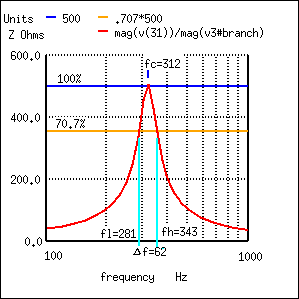 There are several problems that can happen on measurement, if you pretend to measure high Q circuit as the VNA has a reference of 50 Ohm values of R > 600 ohm will be inaccurately measured it propagates errors to results as Fo / Q . The same problem will happen with the same components if you switch to serial configuration where the series equivalent resistor will be very low. Also don?y forget our parasitic capacitance Co it will shift the resonance frequency between configurations. The calibration accuracy is very important also , take care to have very good standards , specially short for series and open for parallel configurations you will work close to these extremes with reasonable quality components. The connections between the VNA port and components under test would be made with care because they also are included on measurement.? In this case for higher Q values the best is to use a transformer coupling with other coil would be a good idea but it introduces a new L? on circuit. ?On coupled inductors you have the self inductance of each one and the mutual inductance. But all depends on the accuracy that you need. ?In some cases a transformer would be used or a balun and the port would be calibrated with them included.? Finally its possible to measure Co if you have a previously measured capacitors. Co depends strongly on frequency , it depends on dielectric properties of winding form… and all you can imagine factors. for air inductors it would be more stable. So the method to measure is very old and used with Q meters. First you need to get resonance at desired measurement frequency and then vary the capacitor a known value and get a new resonant frequency. The idea is to get values around the measurement point. You will have values? (F1,C1) , (F2,C2), (F3,C3)? Then Omega= 2 Pi f and you can plot: ?1/Omega^2 = L. C, as you van see on the plot a made by hand ( sorry for that ) the points represent the measured values ?if you get a few points the green line can be drown as the line that pass by the points on the mean this is the best you can do. If you get more points it will define a curve ?and his pendent is L ( that also varies with frequency) the green line is the tangent to this curve at the desired frequency. C scale are really shifted by Co then it don't cross the ?origin when you project it, so you can determine Co as you can see on plot.? ? I really hope it would be useful. Regards, Patricio.? Ing. Patricio A. Greco Laboratorio de Calibración ISO 17025?AREA: RF/MW? Gral. Martín Rodríguez 2159 San Miguel (1663) Buenos Aires T: +5411-4455-2557 F: +5411-4032-0072
|
|
Re: Tantalum Capacitors
Weren't some of these only identified by the lead length of the positive side? On Thu, Nov 28, 2024 at 6:05?AM Dave_G0WBX via <g8kbvdave=[email protected]> wrote:
|
|
Re: Tantalum Capacitors
开云体育Re:- "Some tantalum capacitors needed a small resistor of a few ohms in series with the supply voltage to limit the dV/dt and inrush current as well."
Oh Yes indeed!? In truth, I suspect all "Tantalum" cap's have a
surge current limit, that if exceeded will do them damage... In the immediate past full time day job, I ended up having to
replace several SMD type 68uF/50V parts (similar to these:
) that were used to
decouple an incoming +20V high current supply, that itself was
switched by a relay contact.? The PSU was rated at several 100W on
that rail. I quite soon (with a bit of online research) discovered they don't tolerate surge currents that well (if at all) but could not convince our product designers of that fact, even by sending them extracts, and complete data sheets from the manufacturer they used. (The relay contact would also pit and fail after some time too.?
Another "schoolboy mistake" they made, but again not interested in
mitigating.? In later versions of that product, the PSU was
commanded On/Off, rather than use a relay on it's output.? It was
a custom multi-rail type by then, so I guess someone else with
more clout than a wholly owned subsidiary doing support and
repairs could wield.) I (like others on this list) fitted electrolytic parts instead, if they fitted inside the module (and other parts of the module, such as nearby components or the board itself were not badly damaged.)? Else, they were fitted to the outside of the case. The data sheet from maker used (Vishay I think in that case, but I cannot be sure of that) also indicated that the larger SMD Tantalum parts, needed "annealing" after soldering to a board, to reduce/remove internal stresses built up during the SMD soldering phase, that could cause premature failure.? Something else our "engineering" types did not want to know, and/or failed to acknowledge. In a past (much earlier) work life, I had first hand experience while working for Tek in the UK, of the great "Tantalum fitted the wrong way round issue" in such instruments as the venerable Tek 465 'scope.? Oddly, they'd often last long enough to just get past the warranty period!? A quiet failure too, the 'scope would just suddenly shutdown, or just fail to power up when needed.? No uncontrolled "Fire and Brimstone" events.? Plus, the bad ones were difficult to spot, unless they sported a small silver "blob" somewhere on their body, but they we found would often fall off during de-casing the instrument. The quickest way to find them was brutal.? Pull the collapsed PSU
rail current limit sense transistor and wait....? Sometimes it
would take another hour, other times a few seconds.? I used to put
the s'cope on a turntable standing on it's rear with the cover
off, so it could be rotated when the smoke came, to find the
culprit.? (With the intensity turned down, and fully de-focused,
in case when a cap' failed, that could result in a static high
intensity beam.) Power down, remove, clean up, install new part, taking great care to fit the right way round!? And re-test.? One instrument went through that three times that I know off.? Most, were just single event failures. Of course, a full performance / calibration check was performed before returning the unit to the customer. In Tek's defence, those parts were the multi coloured bead
types.? Some makes were not exactly obvious which lead was the +ve
from the colours and layout of the markings used.. I still wonder if any survived and "re-polarised" themselves (If Tant' cap's can even do that) and have had a long working life.? I have a 465 and 485, both riddled with the things, both still work well. Regards to All. Dave 'KBV
|
|
Re: VNA Resonance Methodology
开云体育If you reconfigure the LC circuit, as a series resonant element,
I suspect you'll see "Resonance" as a point at/near the SmithChart
centre point, where the L and C almost cancel themselves, leaving
the resistor for the VNA to "see".? Any losses (resistance in the
inductor, or losses in the capacitor) should show as a less than
perfect 50r match at resonance. Try it and see perhaps? 73. Dave 'KBV
|