Re: VNA Resonance Methodology
Sorry : ?Q =Fo/BW?
Ing. Patricio A. Greco
Taller Aeronáutico de Reparación 1B-349
Organización de Mantenimiento?Aeronáutico de la Defensa OMAD-001
Laboratorio de Calibración ISO 17025?AREA: RF/MW?
Gral. Martín Rodríguez 2159
San Miguel (1663)
Buenos Aires
T: +5411-4455-2557
F: +5411-4032-0072
toggle quoted message
Show quoted text
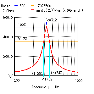
Hi: I’m following this topic and its really interesting. If the VNA port is properly calibrated you can connect any dipole on it and measure impedance. The instrument must to be calibrated at the reference plane this can include a cable for example. In general the resonance frequency Fo happens when the reactive part of impedance nulls. At this frequency you have a resistance Rp. The problem to compute Q in this case is that you need to know L of resonant circuit this is proportional to energy stored on reactive components… Q is a ratio between the lost energy on each cycle and the energy storage on reactive components. You should to disconnect C from circuit and measure L but you never can measure the value of L because you have a parasitic Co … capacitance between turns… so the better way to compute Q is to use the bandwidth the you can measure with VNA. If you plot the modulus of Z and take the bandwidth al 70,7% of the peak Q= BW/Fo.?
There are several problems that can happen on measurement, if you pretend to measure high Q circuit as the VNA has a reference of 50 Ohm values of R > 600 ohm will be inaccurately measured it propagates errors to results as Fo / Q . The same problem will happen with the same components if you switch to serial configuration where the series equivalent resistor will be very low. Also don?y forget our parasitic capacitance Co it will shift the resonance frequency between configurations. The calibration accuracy is very important also , take care to have very good standards , specially short for series and open for parallel configurations you will work close to these extremes with reasonable quality components. The connections between the VNA port and components under test would be made with care because they also are included on measurement.? In this case for higher Q values the best is to use a transformer coupling with other coil would be a good idea but it introduces a new L? on circuit. ?On coupled inductors you have the self inductance of each one and the mutual inductance. But all depends on the accuracy that you need. ?In some cases a transformer would be used or a balun and the port would be calibrated with them included.? Finally its possible to measure Co if you have a previously measured capacitors. Co depends strongly on frequency , it depends on dielectric properties of winding form… and all you can imagine factors. for air inductors it would be more stable. So the method to measure is very old and used with Q meters. First you need to get resonance at desired measurement frequency and then vary the capacitor a known value and get a new resonant frequency. The idea is to get values around the measurement point. You will have values?
(F1,C1) , (F2,C2), (F3,C3)?
Then Omega= 2 Pi f and you can plot: ?1/Omega^2 = L. C, as you van see on the plot a made by hand ( sorry for that ) the points represent the measured values ?if you get a few points the green line can be drown as the line that pass by the points on the mean this is the best you can do. If you get more points it will define a curve ?and his pendent is L ( that also varies with frequency) the green line is the tangent to this curve at the desired frequency. C scale are really shifted by Co then it don't cross the ?origin when you project it, so you can determine Co as you can see on plot.?
? <Graph.png>
I really hope it would be useful.
Regards, Patricio.?
Ing. Patricio A. Greco
Laboratorio de Calibración ISO 17025?AREA: RF/MW?
Gral. Martín Rodríguez 2159
San Miguel (1663)
Buenos Aires
T: +5411-4455-2557
F: +5411-4032-0072
If you reconfigure the LC circuit, as a series resonant element, I suspect you'll see "Resonance" as a point at/near the SmithChart centre point, where the L and C almost cancel themselves, leaving the resistor for the VNA to "see".? Any losses (resistance in the inductor, or losses in the capacitor) should show as a less than perfect 50r match at resonance.
Try it and see perhaps? 73. Dave 'KBV
|
Re: VNA Resonance Methodology
Hi: I’m following this topic and its really interesting. If the VNA port is properly calibrated you can connect any dipole on it and measure impedance. The instrument must to be calibrated at the reference plane this can include a cable for example. In general the resonance frequency Fo happens when the reactive part of impedance nulls. At this frequency you have a resistance Rp. The problem to compute Q in this case is that you need to know L of resonant circuit this is proportional to energy stored on reactive components… Q is a ratio between the lost energy on each cycle and the energy storage on reactive components. You should to disconnect C from circuit and measure L but you never can measure the value of L because you have a parasitic Co … capacitance between turns… so the better way to compute Q is to use the bandwidth the you can measure with VNA. If you plot the modulus of Z and take the bandwidth al 70,7% of the peak Q= BW/Fo.?
There are several problems that can happen on measurement, if you pretend to measure high Q circuit as the VNA has a reference of 50 Ohm values of R > 600 ohm will be inaccurately measured it propagates errors to results as Fo / Q . The same problem will happen with the same components if you switch to serial configuration where the series equivalent resistor will be very low. Also don?y forget our parasitic capacitance Co it will shift the resonance frequency between configurations. The calibration accuracy is very important also , take care to have very good standards , specially short for series and open for parallel configurations you will work close to these extremes with reasonable quality components. The connections between the VNA port and components under test would be made with care because they also are included on measurement.? In this case for higher Q values the best is to use a transformer coupling with other coil would be a good idea but it introduces a new L? on circuit. ?On coupled inductors you have the self inductance of each one and the mutual inductance. But all depends on the accuracy that you need. ?In some cases a transformer would be used or a balun and the port would be calibrated with them included.? Finally its possible to measure Co if you have a previously measured capacitors. Co depends strongly on frequency , it depends on dielectric properties of winding form… and all you can imagine factors. for air inductors it would be more stable. So the method to measure is very old and used with Q meters. First you need to get resonance at desired measurement frequency and then vary the capacitor a known value and get a new resonant frequency. The idea is to get values around the measurement point. You will have values?
(F1,C1) , (F2,C2), (F3,C3)?
Then Omega= 2 Pi f and you can plot: ?1/Omega^2 = L. C, as you van see on the plot a made by hand ( sorry for that ) the points represent the measured values ?if you get a few points the green line can be drown as the line that pass by the points on the mean this is the best you can do. If you get more points it will define a curve ?and his pendent is L ( that also varies with frequency) the green line is the tangent to this curve at the desired frequency. C scale are really shifted by Co then it don't cross the ?origin when you project it, so you can determine Co as you can see on plot.?
?
I really hope it would be useful.
Regards, Patricio.?
Ing. Patricio A. Greco
Laboratorio de Calibración ISO 17025?AREA: RF/MW?
Gral. Martín Rodríguez 2159
San Miguel (1663)
Buenos Aires
T: +5411-4455-2557
F: +5411-4032-0072
toggle quoted message
Show quoted text
If you reconfigure the LC circuit, as a series resonant element,
I suspect you'll see "Resonance" as a point at/near the SmithChart
centre point, where the L and C almost cancel themselves, leaving
the resistor for the VNA to "see".? Any losses (resistance in the
inductor, or losses in the capacitor) should show as a less than
perfect 50r match at resonance.
Try it and see perhaps? 73. Dave 'KBV
|
Weren't some of these only identified by the lead length of the positive side?
Re:-
"Some tantalum capacitors needed a small resistor of a few ohms
in series with the supply voltage to limit the dV/dt and inrush
current as well."
Oh Yes indeed!? In truth, I suspect all "Tantalum" cap's have a
surge current limit, that if exceeded will do them damage...
In the immediate past full time day job, I ended up having to
replace several SMD type 68uF/50V parts (similar to these:
) that were used to
decouple an incoming +20V high current supply, that itself was
switched by a relay contact.? The PSU was rated at several 100W on
that rail.
I quite soon (with a bit of online research) discovered they
don't tolerate surge currents that well (if at all) but could not
convince our product designers of that fact, even by sending them
extracts, and complete data sheets from the manufacturer they
used.
(The relay contact would also pit and fail after some time too.?
Another "schoolboy mistake" they made, but again not interested in
mitigating.? In later versions of that product, the PSU was
commanded On/Off, rather than use a relay on it's output.? It was
a custom multi-rail type by then, so I guess someone else with
more clout than a wholly owned subsidiary doing support and
repairs could wield.)
I (like others on this list) fitted electrolytic parts instead,
if they fitted inside the module (and other parts of the module,
such as nearby components or the board itself were not badly
damaged.)? Else, they were fitted to the outside of the case.
The data sheet from maker used (Vishay I think in that case, but
I cannot be sure of that) also indicated that the larger SMD
Tantalum parts, needed "annealing" after soldering to a board, to
reduce/remove internal stresses built up during the SMD soldering
phase, that could cause premature failure.? Something else our
"engineering" types did not want to know, and/or failed to
acknowledge.
In a past (much earlier) work life, I had first hand experience
while working for Tek in the UK, of the great "Tantalum fitted the
wrong way round issue" in such instruments as the venerable Tek
465 'scope.? Oddly, they'd often last long enough to just get past
the warranty period!? A quiet failure too, the 'scope would just
suddenly shutdown, or just fail to power up when needed.? No
uncontrolled "Fire and Brimstone" events.? Plus, the bad ones were
difficult to spot, unless they sported a small silver "blob"
somewhere on their body, but they we found would often fall off
during de-casing the instrument.
The quickest way to find them was brutal.? Pull the collapsed PSU
rail current limit sense transistor and wait....? Sometimes it
would take another hour, other times a few seconds.? I used to put
the s'cope on a turntable standing on it's rear with the cover
off, so it could be rotated when the smoke came, to find the
culprit.? (With the intensity turned down, and fully de-focused,
in case when a cap' failed, that could result in a static high
intensity beam.)
Power down, remove, clean up, install new part, taking great care
to fit the right way round!? And re-test.? One instrument went
through that three times that I know off.? Most, were just single
event failures.
Of course, a full performance / calibration check was performed
before returning the unit to the customer.
In Tek's defence, those parts were the multi coloured bead
types.? Some makes were not exactly obvious which lead was the +ve
from the colours and layout of the markings used..
I still wonder if any survived and "re-polarised" themselves (If
Tant' cap's can even do that) and have had a long working life.? I
have a 465 and 485, both riddled with the things, both still work
well.
Regards to All.
Dave 'KBV
|
Re: VNA Resonance Methodology
If you reconfigure the LC circuit, as a series resonant element,
I suspect you'll see "Resonance" as a point at/near the SmithChart
centre point, where the L and C almost cancel themselves, leaving
the resistor for the VNA to "see".? Any losses (resistance in the
inductor, or losses in the capacitor) should show as a less than
perfect 50r match at resonance.
Try it and see perhaps?
73.
Dave 'KBV
|
What series of Microdye radios did you service? I worked on many of them at their factory in Ocala. We still produced some 1100 series, 1200, 1400, 700/1620, and the RCB2000 during my time there. They had also built their many 1100 series satellite receivers at that plant. We had some VXI boards for custom Telemetry products, but they were handled by the Engineering techs. We were using mostly SMD or molded tubular Tantalum during the 1997 to 2001 period. I don't recall any dipped tantalum, so the older designs must have ad the borads spn to change to the tubular style.
So, on the subject of those dipped "orange drop" tants: they suck.? They go bad with age seemingly, because I am told, the seal is not made to last and they dry out and short. I have seen literally hundreds of these in Watkins Johnson & Microdyne radios, EIP counters, HP gear (not used often) go bad, sometimes burning and marring the circuit board. They are my first suspect when looking for shorted power supply lines.
Now, on the other hand, hermetically sealed mil type of tants seem to last forever.
I have seen stashes of the dipped type go bad, just sitting on the shelf. I will not use them and when I get some in a box of parts, I get rid of them.
True experiences, not conjecture. They have LONG outlived their economic lifetime in our gear.
|
Re: HP 8341B 1992 firmware version
Hi Saevar, Dmitrij,
Thank you very much for all the information. I will try these then.
Thanks, Wojciech
|
They have smaller ESR (also should be able to reach higher frequencies). I replace them with low ESR high temp aluminum ones (usually 50V). Additionally one can add the 100nF SMD between the legs.
?
In computers they are also the pain. Look to Adrian basement channel on youtube. He repaired some computer where the caps were used on the bus and was explaining, that if one fails usually the other goes bad at the next turn on after the repair.
|
Re: VNA Resonance Methodology
Jinxie,
Bravo for the fine notes and topic. Happy to send you links or pix if you are interested.
As a kid I wound Tesla coils since 1956 (!) of increasing sizes.
By 1970s..1980s got classic Boonton 260A Q meter (boatanchor)
and at Silicon Valley ham fleas many Boonton/Measurements GDO.
The Tesla coils are always air wound solenoids,
Primary and secondary should be tuned to same freq, normally 20kHz..500 kHz.
See our old friend Gred LEYH at LOD.ORG
Classic GDO and Q meter were VERY handy to design and tune Teslas coils.
Boonton supplied calibrated stable L and Q standards in metal cans and bannana plug to calibrate.
We can connect, if you PM email
Amicalment
Jon
|
Forgot to mention - one thing I've noticed is that much more modern non-hermetic Ta caps like encountered in surface-mount on things like PCs and laptops, don't seem to be much trouble. I'd expect that more modern components of all types should benefit from technical advancements.
?
Ed
|
So, on the subject of those dipped "orange drop" tants: they suck.? They go bad with age seemingly, because I am told, the seal is not made to last and they dry out and short. I have seen literally hundreds of these in Watkins Johnson & Microdyne radios, EIP counters, HP gear (not used often) go bad, sometimes burning and marring the circuit board. They are my first suspect when looking for shorted power supply lines.
Now, on the other hand, hermetically sealed mil type of tants seem to last forever.
I have seen stashes of the dipped type go bad, just sitting on the shelf. I will not use them and when I get some in a box of parts, I get rid of them.
True experiences, not conjecture. They have LONG outlived their economic lifetime in our gear.
|
I think you'll find that your stock of non-hermetic (like dipped) Ta caps are less reliable than expected, due to environmental issues like humidity after many years, even if never used before. The operating voltage versus specified is a big factor as we've seen over the years, but there's more to it than that. I have quite a few old Ta caps in dipped and hermetic (like Sprague 105D style) forms, and still prefer them over any vintage of Al parts up to a practical limit around 300 uF or so. The hermetic ones are the most reliable, especially with age (but not immune to problems).
?
The old dipped ones should still be acceptable, but maybe de-rate them voltage-wise even more than usual for best results. I think there are quality vs brand issues too, but that's hard to figure out. More than once I've thought I figured out which ones to use and which to avoid, only to be proven wrong later. The ones I distrust the most are the color-coded "rainbow" types often seen in Tek equipment from the 1970s-1980s. But, I've been wrong on that enough times too.
?
Ed
|
Some tantalum capacitors needed a small resistor of a few ohms in series with the supply voltage to limit the dV/dt and inrush current as well.
Hugh Gilbert
Hello Gary, Tantalum capacitors’ working Voltage rating is for marketing purposes only. The Arrhenius equation regarding time to failure applies. As you approach the rated Voltage, the time to failure gets shorter and shorter. When I replace tantalum capacitors, I use ones rated (marketed) with double my expected operating Voltage. When tantalum capacitors first became available, printed wiring board designers took advantage of the smaller size of tantalum capacitors and crammed them onto the board.? When I repair a board, if there’s enough room, I generally replace tantalum capacitors with good-quality low-ESR electrolytic capacitors. 73 de Brian, VK2GCE ? ? I'm sure we've all repaired some equipment where a tantalum capacitor has shorted.? I lived for 30 years in San Jose, and collected lots of parts, including a lifelong supply of teardrop tantalum capacitors of various values and voltages. I have used these in projects over the years with no trouble. But over the past few years they seem to fail immediately. Today I had to replace a tantalum capacitor in an HP 5328A counter, and the replacement immediately failed. I placed another one on a power supply and ran the voltage up to 15 volts for a 20 volt capacitor. The supply briefly went in to current? limiting multiple times before the capacitor failed completely. Do tantalum capacitors degrade with time with no voltage supplied? Or do I just have a bunch of poor quality parts? Any information would be appreciated - although regardless, I think it may be time to toss my collection of tantalum capacitors.
|
Hello Gary, Tantalum capacitors’ working Voltage rating is for marketing purposes only. The Arrhenius equation regarding time to failure applies. As you approach the rated Voltage, the time to failure gets shorter and shorter. When I replace tantalum capacitors, I use ones rated (marketed) with double my expected operating Voltage. When tantalum capacitors first became available, printed wiring board designers took advantage of the smaller size of tantalum capacitors and crammed them onto the board. ?When I repair a board, if there’s enough room, I generally replace tantalum capacitors with good-quality low-ESR electrolytic capacitors. 73 de Brian, VK2GCE ?
toggle quoted message
Show quoted text
From: [email protected] [mailto:[email protected]] On Behalf Of Gary Appel
Sent: Thursday, 28 November 2024 12:34 PM
To: [email protected]
Subject: [HP-Agilent-Keysight-equipment] Tantalum Capacitors? I'm sure we've all repaired some equipment where a tantalum capacitor has shorted.? I lived for 30 years in San Jose, and collected lots of parts, including a lifelong supply of teardrop tantalum capacitors of various values and voltages. I have used these in projects over the years with no trouble. But over the past few years they seem to fail immediately. Today I had to replace a tantalum capacitor in an HP 5328A counter, and the replacement immediately failed. I placed another one on a power supply and ran the voltage up to 15 volts for a 20 volt capacitor. The supply briefly went in to current? limiting multiple times before the capacitor failed completely. Do tantalum capacitors degrade with time with no voltage supplied? Or do I just have a bunch of poor quality parts? Any information would be appreciated - although regardless, I think it may be time to toss my collection of tantalum capacitors.
|
I'm sure we've all repaired some equipment where a tantalum capacitor has shorted.?
?
I lived for 30 years in San Jose, and collected lots of parts, including a lifelong supply of teardrop tantalum capacitors of various values and voltages. I have used these in projects over the years with no trouble. But over the past few years they seem to fail immediately. Today I had to replace a tantalum capacitor in an HP 5328A counter, and the replacement immediately failed. I placed another one on a power supply and ran the voltage up to 15 volts for a 20 volt capacitor. The supply briefly went in to current? limiting multiple times before the capacitor failed completely.
?
Do tantalum capacitors degrade with time with no voltage supplied? Or do I just have a bunch of poor quality parts?
?
Any information would be appreciated - although regardless, I think it may be time to toss my collection of tantalum capacitors.
?
Gary Appel
|
Re: VNA Resonance Methodology
On Wed, Nov 27, 2024 at 11:05 PM, Tom Lee wrote:
Thanks very much, jmr, for going to the trouble of running the numbers through Genesys. You've provided a valuable cross-check of my cheese formulas, which give L = 64uH, Q = 190, and srf = 16MHz. The inductance comes out quite close (thanks to Wheeler). The Q formula is extremely crude (assumes resistance for close-wound coils is 4x the textbook skin resistance), but seems to be in the right general ballpark, if optimistic. The srf formula comes from simplifying a helical transmission line formula. From your curves, I infer that it's giving a reasonable approximation.
Thanks. It's a long time since I wrote that software program but (to compute Q) I think the program uses a map based on empirical measurements made decades ago by Butterworth and Medhurst some time around 1947? Both noted that the AC resistance changes from the skin effect model of a straight wire and they produced tables of how it changes based on the L/D ratio of the coil and also on the wire to gap ratio. So I plotted all this data in a huge 3D map in my software and the program code then interpolates between the data points as required. I can't remember whose lookup tables I eventually used, it might even have been a later revision of the data I found in a modern text book. I do the same for the impact of the self capacitance of the coil in that I mapped all the data for this as well.
?
Before this I had to do it all in an excel spreadsheet and manually navigate the tables to find the various fudge factors for Q and capacitance etc.
?
The Genesys air solenoid model seems to work quite well although for wideband stuff at work I prefer to use a VNA based model or a physical model I developed at work many years ago. The Genesys model (and my software program) falls apart near the first resonance mode so it is hopeless for wideband design work. My physical model is transmission line based although it is a bit more involved than just a transmission line. I did all this at work many years ago in order to be able to understand how to make better (ultra wideband) bias tees and how to make RF filters work over wider bandwidths (especially highpass filters). The aim was to be able to model the various resonance modes in a solenoid such that the model could be used in a simulator.
?
?
|
Re: VNA Resonance Methodology
Thanks. It is a bit hard to see the blue arc in the image so I've thickened up the blue trace width and plotted it again without the markers. The top of the blue arc corresponds with the start frequency of 1 MHz and the bottom of the arc corresponds with the stop frequency of 2 MHz.?
?
1.45 MHz is roughly at the centre of the arc at 3 o'clock on the smith chart (very close to being an open circuit).
?
|
Re: HP 6114A - looking for R8A, 15.82K 0.1% 1ppm resistor
Maybe because I also wrote them?...?
The ones I ordered before - bulk foil Z201 - are not smd, though, and I wonder if that has to do with them coming up with an MOQ (the VSMP1206, which is what I think you ordered, are quite a bit cheaper). I inaccurately assumed you're looking for a through hole type.? But hopefully they reassess their stance and do this for you. Radu.?
I asked for the 1206 size as I only needed 1/8W and the price was less.
Here's the part ?
?
Looks like I did get a followup email after declining moving forward saying "Let me ask manufacturing as maybe the unit price will be higher just for one."
?
Dave
?
|
Re: VNA Resonance Methodology
Thanks very much, jmr, for going to the trouble of running the numbers through Genesys. You've provided a valuable cross-check of my cheese formulas, which give L = 64uH, Q = 190, and srf = 16MHz. The inductance comes out quite close (thanks to Wheeler). The Q formula is extremely crude (assumes resistance for close-wound coils is 4x the textbook skin resistance), but seems to be in the right general ballpark, if optimistic. The srf formula comes from simplifying a helical transmission line formula. From your curves, I infer that it's giving a reasonable approximation.
Thanks again!
-- Cheers
Tom
--
Prof. Thomas H. Lee
Allen Ctr., Rm. 205
420 Via Palou Mall
Stanford University
Stanford, CA 94305-4070
toggle quoted message
Show quoted text
On 11/27/2024 1:59 PM, jmr via groups.io wrote: If it helps add some confidence to this stuff, I used the air cored solenoid model in Genesys to predict the inductance and Q vs frequency for your coil. 49 turns 31mm diameter length 22mm wire diameter 0.4mm.
This model in Genesys is typically quite good and I'm lucky to have access to CAD tools like this. Genesys predicts 65uH and a Q of 122 at 1.45 MHz as in the screen capture below.
|
Re: VNA Resonance Methodology
Richard,
It is a short blue arc at the right edge of the chart.? Pretty hard to see unless you save the image and enlarge it.
--John Gord
?
On Wed, Nov 27, 2024 at 02:48 PM, Richard Knoppow wrote:
I see zilch on the chart. Did something get left out?
On 11/27/2024 2:16 PM, jmr via groups.io wrote:
Here's what you should see on a smith chart with a start frequency of 1
MHz and a stop frequency of 2 MHz when resonated at 1.45 MHz with a
187pF cap and with a series 50R resistor inline.
--
Richard Knoppow
Los Angeles
WB6KBL
SKCC 19998
|
