Re: How do I use these PSU output covers?
Haha - those are just Heycos - they're ubiquitous and have been around for ever.
Ed
|
Re: How do I use these PSU output covers?
You're right. The cover holes are designed to use cord strain relief grommets similar to these:
The "not round" aperture is designed to be close to the "double D" hole the strain reliefs require.? I believe the manual contains recommended manufacturer part numbers in the parts list. There was an installation guide that showed the various installation options. It may have also provided compatible part numbers.
All that said, I never used the strain reliefs.? I'd knock out the appropriate size blocks and use a conventional round grommet or Heyco snap-in and tie the wires off at a stable attachment point. The knockouts are designed to have a small flat blade screwdriver inserted in the center slot as a lever to twist them out.
While you can use just about anything for a sense wire, I usually use 18 AWG or larger wire, chiefly for mechanical robustness.
IIRC, this series of supply have an internal ~100 ohm resistor between the output and sense lines so the output control loop is closed even if sense wires are not used. If you need the current these beasts can supply, you should be using sense lines even with large gauge supply wire.
Oz
|
Re: 54615B Agilent Scope Amplitude Low When Measuring 120V AC
As long as one side of the mains is nominally at "earth ground," you can simply connect only the tip of a suitably rated attenuator (10x or 100x) probe to any point. Use DC coupling to avoid any LF rolloff issues. The line side should show the full line voltage waveform. The neutral side should show the neutral/ground junk, which should be nearly zero in the scale of things. Do NOT connect the ground clip from the probe - it's actually best to remove it from the probe if it clips in, or tape it over if not, to avoid inadvertently making a connection. At low frequencies the probe ground doesn't matter.
As others have mentioned, the line waveform is remarkably distorted, so don't bother comparing DMM, true RMS etc measurements with the time domain scope display. The scope will show what it actually looks like, as accurately as the probe/scope combo can.
Ed
|
The RF TIP is simply an accessory that attaches to the end of the oscilloscope probe, very useful for reducing interference pickup during low amplitude signals. If you don't have one, you can build an equivalent with a single stranded wire. The goal is to make ground contact at the tip of the probe ... as shown in the picture. ? -Yves ? ? So I was perusing the HPAK 6632B manuals and under performance testing it requires a "1:1 probe with an RF tip."? Elsewhere under PARD testing it says? "Set the oscilloscope's bandwidth limit to 20 MHz and use an RF tip on the oscilloscope probe".??
My question is what exactly is an RF probe tip?
|
Re: [DM] [HP-Agilent-Keysight-equipment] 75 GHz sig gen
hi mike?
I thought i had it bad? but please keep me in mind for any wave guide components above 80 Ghz and your giga tronics?
regards Paul?
|
There is a variety of probe tips used for RF measurements,? unless the procedure identifies a specific HP probe part number you have a lot of latitude for a measurement that only requires 20 MHz of bandwidth. Often you use the sharp pointed tip and the ground spring attachment that lets you probe an RF trace right next to a ground. The BNC adapter is also useful for RF measurements made on female BNCs, but I don't think that applies here.? The typical scope probes tips HPAK includes? with 1k, 2k and 3k scopes is shown in the photo below, anything that can connect to the signal and a ground and eliminates the flying ground clip should be more than adequate up to 20 MHz. Ted WR4T 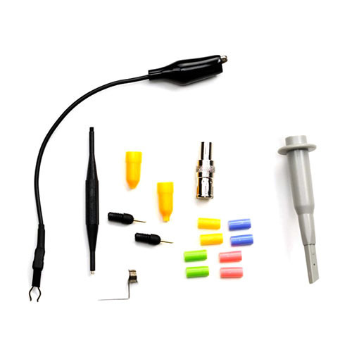
|
Re: Sample preparation for Impedance Analyzer
Hi:
I have posted your photo of the 16091A and added an explanation as best as I can remember it at:
The small bore main body was not in the photo.
--
Have Fun,
Brooke Clarke
axioms:
1. The extent to which you can fix or improve something will be limited by how well you understand how it works.
2. Everybody, with no exceptions, holds false beliefs.
|
[DM] [HP-Agilent-Keysight-equipment] 75 GHz sig gen
I do not have a photo right now, however, you can see part of it in photo number 1210 in this bunch of photos of my TE that are all FS, . It is the bottom unit on the bench on the right. Only half is visible in that photo. These photos were taken with the intent that someone would come over and look at the stuff they are interested in, as they are al too heavy for me to mail. I would think the best way to get your I/Q outputs would be to get a HF generator that has I/Q outputs and then use two mixers to mix it with the output of the GHz generator. You should make sure that the mixers were phase matched at your intended output frequency. The other issue will be the unwanted image may be too close if the HF is too low. Using filters to remove the image is again a challenge as getting filters to be phase matched that close at GHz frequencies will be difficult. Essentially the Weaver method without summing the outputs. 73 – Mike ? Mike B. Feher, N4FS 89 Arnold Blvd. Howell NJ 07731 848-245-9115 ?
toggle quoted message
Show quoted text
From: Paul Bicknell < admin@...> Sent: Wednesday, November 17, 2021 1:28 PM To: n4fs@...Subject: [DM] [HP-Agilent-Keysight-equipment] 75 GHz sig gen ? Hi Mike?
just a quick question could you please let me have a picture of your 75 GHz sig gen and how much thy go for as my multiplayer has an input of 20 ghz so the harmonics at 75 Ghz are higher?
Regards Paul
|
53131A Counter Interpolator Fail Error
My 53131A sometimes throws up the "Interp Fail" message, although 99% of the time it works well, and passes the power on test.? I can find nothing relevant to this in the Service manual except a brief note about calibrating the Interpolator over HPIB, and another mention that suggests replacing the mother board, which I am not inclined to do.? Has anyone seen this and if so, what was the solution?
Thanks,
Dan
ac6ao
|
Re: Query about 40 GHz sig gens
Hi Mike?
Thank you for the information there are probably only a few Giga tronics multipliers? or sig generators that go up to 75 Ghz still in existence probably less than 10 in this group
as IQ is? new to me and i haven't started to play with it yet?
what happens to the IQ signal when you go through a multiplayer for example? X 2? other than I assume the jitters multiplying by 2?
Regards Paul?
|
Re: 54615B Agilent Scope Amplitude Low When Measuring 120V AC
I used to work in the EE lab of a university, can't tell you how many times students would bring us a scope probe with a burned up ground wire.? We had the option of an isolation xformer or even use a differential input. If we knew the student was measuring in the area of 120, 240, or 208 three phase, we would offer assistance, but we usually heard a bang as they blew a ground. Don't ever recall any actual damage to a scope though. ?
|
Re: How do I use these PSU output covers?
Sometimes the external sensing may be linked with diodes instead of resistors - that sets a limit on how far off the output can go, in case the sensing is disconnected, but it's still closed-loop. If there's no bypass link devices at all to the sense lines, then when disconnected, it would truly go open-loop, with bad results.
Ed
|
Re: How do I use these PSU output covers?
Maybe they supplied a bag of special HP oval grommets with each supply...
Well you saw my solution when using heavy cable - throw the box away and do it properly. Underneath the heatshrink are lugs crimped to the cable and bolted to the terminals with M8 (?) bolts.
> I would have expected Agilent to link them via a resistor (say 100 ohm), so there's always feedback
Indeed. I would have expected the same. But on mine the offset is significant. Bad design. It should either work properly or not at all without the links, like any other supply I've used. This problem isn't just a fault in mine - I took that pic to help out someone who had the same problem,?but his links and connector were missing. Just to add to the confusion the built-in semi-auto calibration routine can almost but not quite calibrate out the offset, so after a cal?without the links there are errors with or without the loopback.
That's my only grumble. The supplies refuse to die however I mistreat them..?
On Wed, 17 Nov 2021 at 14:14, Dr. David Kirkby, Kirkby Microwave Ltd < drkirkby@...> wrote: On Tue, 16 Nov 2021 at 10:24, Peter Hamilton < lists@...> wrote:
I have a couple of these supplies. When I'm using thin cables I bring them out of the slots on the lower face of the cover (I also use remote sensing with thin cables).?
If you don't want remote sensing you still need to loop back the sense inputs under that cover, or you'll see a significant output voltage error. Fitted by default by HP, but sometimes they and the annoyingly difficult to find connector get lost.
Mine is a bit different - the feedback terminals are not under the cover, but elsewhere on the back. I would have expected Agilent to link them via a resistor (say 100 ohm), so there's always feedback, but if one connects actual cables the resistance will be much lower than 100 ohm, so it will be irrelevant.
I'm puzzled how one is supposed to use the small outlets anyway. One can't fit a grommet there properly, as a bit on the back gets in the way. Just to add to the complication, the surface on the back is not flat, but has some thin strips of plastic, aout 1 mm wide and 2 mm deep.
My cables are too thick to fit through the area intended for the bus bars if connecting two instruments in parallel.
Why would HP design that so whatever knockout you remove, you don't get a circular hole? The whole thing seems a bit naff to me.
Dave
|
Re: Query about 40 GHz sig gens
Paul – Mine is all in one large package. The multipliers are internal. It has an SMA for the basic generator up to 26 GHz, as I recall and WGs for the X2 an X3 outputs. All leveled of course. 73 – Mike ? Mike B. Feher, N4FS 89 Arnold Blvd. Howell NJ 07731 848-245-9115 ?
toggle quoted message
Show quoted text
From: [email protected] <[email protected]> On Behalf Of Paul Bicknell
Sent: Wednesday, November 17, 2021 4:57 AM
To: [email protected]
Subject: Re: [HP-Agilent-Keysight-equipment] Query about 40 GHz sig gens? Hi Mike ? Just one question is your Gigatronics generator for 75 Ghz an external multiplier? ?As I have the Gigatronics frequency extender 875? that also goes to 75 Ghz ? Jim Regarding Anritsu I have recently been talking to Anritsu? regarding information on old optical equipment? of which they couldn’t help me with any service information just operator ? Regarding on line has HP-Agilent-Keysight-stopped putting manuals on line as I do not seem to be able to find them ? ? Regards Paul ? ? ? I have a Gigatronics generator that goes up to 75 GHz. It does sweep but no I/Q outputs. I would think even now that would be difficult over a wide frequency range. You may have to do that externally over a limited BW. 73 - Mike ? Mike B. Feher, N4FS 89 Arnold Blvd. Howell NJ 07731 848-245-9115 ? -----Original Message-----
From: [email protected] <[email protected]> On Behalf Of ac0xu
Sent: Tuesday, November 16, 2021 9:00 PM
To: [email protected]
Subject: [HP-Agilent-Keysight-equipment] Query about 40 GHz sig gens ? I am looking for a 40 GHz sig gen. Do not need sweep. Would like basic internal modulation capabilities and I/Q inputs if possible. ? Any recommendations for something affordable?? I have seen a lot of Anritsu siggens for sale on Ebay recently at plausible prices. I not e that Anritsu just seems to completely cut off support for older models - a policy which does not encourage me. Are Anritsu units reliable? ? What about Agilent units?? Other brands? ? Thanks- ? Jim ? ? ? ? ?
|
Re: How do I use these PSU output covers?
On Tue, 16 Nov 2021 at 10:24, Peter Hamilton < lists@...> wrote:
I have a couple of these supplies. When I'm using thin cables I bring them out of the slots on the lower face of the cover (I also use remote sensing with thin cables).?
If you don't want remote sensing you still need to loop back the sense inputs under that cover, or you'll see a significant output voltage error. Fitted by default by HP, but sometimes they and the annoyingly difficult to find connector get lost.
Mine is a bit different - the feedback terminals are not under the cover, but elsewhere on the back. I would have expected Agilent to link them via a resistor (say 100 ohm), so there's always feedback, but if one connects actual cables the resistance will be much lower than 100 ohm, so it will be irrelevant.
I'm puzzled how one is supposed to use the small outlets anyway. One can't fit a grommet there properly, as a bit on the back gets in the way. Just to add to the complication, the surface on the back is not flat, but has some thin strips of plastic, aout 1 mm wide and 2 mm deep.
My cables are too thick to fit through the area intended for the bus bars if connecting two instruments in parallel.
Why would HP design that so whatever knockout you remove, you don't get a circular hole? The whole thing seems a bit naff to me.
Dave
|
Re: Replacing missing button cap(s) - HP 339A
In message <fee9c335-a61c-f573-993b-6d09a4bae288@...>, Dave McGuire <mcguire@...> writes
Jeff, there's more to life than money, and things have value other
than pure dollars. I get that some people don't process that, but it's
a fact.
Indeed! I am reminded of this following comment by Daniel Gooch on Isambard Kingdom Brunel the great Victorian engineer who's railways stations and structures are still in use today some 160 years after his death.. "By his death the greatest of England's engineers was lost, the man with the greatest originality of thought and power of execution, bold in his plans but right. The commercial world thought him extravagant; but although he was so, great things are not done by those who sit down and count the cost of every thought and act". -- Tony Sayer
|
Re: Query about 40 GHz sig gens
HP 70340A option Z40 but no I/Q input.
On Wednesday, November 17, 2021, 03:00:18 AM GMT+1, ac0xu <james.schatzman@...> wrote:
I am looking for a 40 GHz sig gen. Do not need sweep. Would like basic internal modulation capabilities and I/Q inputs if possible.
Any recommendations for something affordable?? I have seen a lot of Anritsu siggens for sale on Ebay recently at plausible prices. I not e that Anritsu just seems to completely cut off support for older models - a policy which does not encourage me. Are Anritsu units reliable?
What about Agilent units?? Other brands?
Thanks-
Jim
|
Re: Query about 40 GHz sig gens
Hi Mike ? Just one question is your Gigatronics generator for 75 Ghz an external multiplier? ?As I have the Gigatronics frequency extender 875? that also goes to 75 Ghz ? Jim Regarding Anritsu I have recently been talking to Anritsu? regarding information on old optical equipment? of which they couldn’t help me with any service information just operator ? Regarding on line has HP-Agilent-Keysight-stopped putting manuals on line as I do not seem to be able to find them ? ? Regards Paul ? ?
toggle quoted message
Show quoted text
From: [email protected] [mailto:[email protected]] On Behalf Of Mike Feher
Sent: 17 November 2021 02:11
To: [email protected]
Subject: Re: [HP-Agilent-Keysight-equipment] Query about 40 GHz sig gens? I have a Gigatronics generator that goes up to 75 GHz. It does sweep but no I/Q outputs. I would think even now that would be difficult over a wide frequency range. You may have to do that externally over a limited BW. 73 - Mike ? Mike B. Feher, N4FS 89 Arnold Blvd. Howell NJ 07731 848-245-9115 ? -----Original Message-----
From: [email protected] <[email protected]> On Behalf Of ac0xu
Sent: Tuesday, November 16, 2021 9:00 PM
To: [email protected]
Subject: [HP-Agilent-Keysight-equipment] Query about 40 GHz sig gens ? I am looking for a 40 GHz sig gen. Do not need sweep. Would like basic internal modulation capabilities and I/Q inputs if possible. ? Any recommendations for something affordable?? I have seen a lot of Anritsu siggens for sale on Ebay recently at plausible prices. I not e that Anritsu just seems to completely cut off support for older models - a policy which does not encourage me. Are Anritsu units reliable? ? What about Agilent units?? Other brands? ? Thanks- ? Jim ? ? ? ? ?
|
Re: HP8011A Pulse Gen w/ Burst Mode
Hello!
I have a strange problem with my HP8011A Pulse Gen. It has a push switch behind the attenuator push switches and this "extra" switch has a mechanical linkage arm that is loose. I cannot see where the bent plastic linkage arm goes and what it does.? Just flopping around.
I cannot find a pic or reference in the online manuals.
It looks like it may have attached to one of the attenuator settings. Any info out there? Seems to not really affect anything as the pulse gen works "fairly" normally.
Thanks
Jeff
|
Re: 54615B Agilent Scope Amplitude Low When Measuring 120V AC
All very interesting input.
I've only measured the hot side of an AC plug a few times in my years. This most recent time was to show someone what 60Hz from an outlet looks like for real.
I don't remember every connecting the ground on the scope probe as I just leave it dangling.
Most likely this would all make more sense if I someone was physically showing the connections and/or how one could get injured. Personally it seems like very little can go wrong providing one doesn't slip with the probe and short both hot and neutral (or hot to Earth ground).
The other way to get injured would be to unplug the scope probe and accidentally touch the end while the probe is connected to the hot.
In any case, I don't plan to measure the hot directly again, but sense this scope has a roll over or something causing the higher voltage measurements to show lower than they are.
|

