
Keyboard Shortcuts
ctrl + shift + ? :
Show all keyboard shortcuts
ctrl + g :
Navigate to a group
ctrl + shift + f :
Find
ctrl + / :
Quick actions
esc to dismiss
Likes
Search
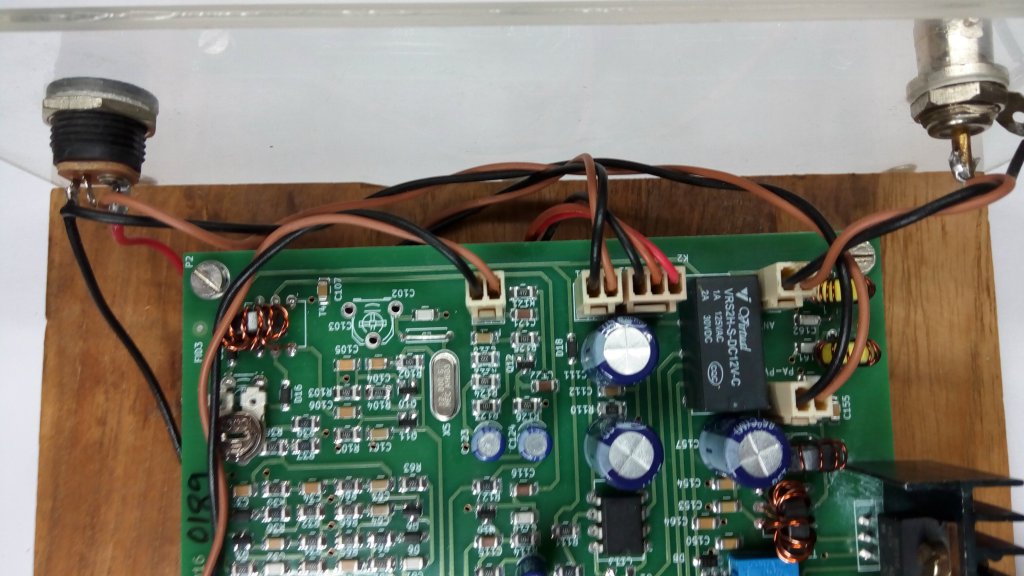
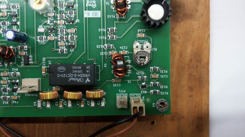
Bitx 40 12 volt power plug-in connector help please 4 wires go to? I'm getting stuck trying to figure out , 2 black I assume are grounds, the brown 12 volt positive, don't know where the red go's Thanks for any help.
|
The black wires go to the ground terminal on the jack. There brown wires go to one side of the power switch. You supply a wire (maybe you have some left over from trimming other wires) from the other side of the power switch to the plus side of the plug. Better is to put a fuse in line with your that last wire but the type and value are debatable. I have a 3 amp fuse in there but suspect a higher amp fast blow would protect the circuit better from the "fat fingered shorts" that I tend to make versus more complicated circuit failures that I know nothing about.
Related: I use the shunt pin on the jack to switch between external power plug and an internal x8 AA battery pack. Connect the battery ground with the others on the plug. Connect the plus wire from the battery pack to the shunt pin on the jack. Done!? It's also possible to use the shunt on a second jack (not supplied) to automatically switch in addition volts from a second power source or to use the volts from the first jack if nothing is plugged into the second plug (but there will be sad faces if the two supplies are not isolated.) Speaker jacks (often) have shunts as well that can switch between? external and internal speakers. I think it's easier to figure out what the pins one the jack do when you know what they're used for. Hope that helps! |
|
Wording in the instructions may be a bit confusing.? The 4th wire is for connecting separate DC power to the RF PA section.? This lets you use higher voltage on the transmitter output stage than the 12V used for other parts of the rig. Arv _._ Step 2: DC Power ConnectionsThe DC power from the socket goes to the board through the on/off switch on the volume control. From the ON/OFF switch, route the power a?parallel connection also goes to the transmitter power amplifier. This is kept as a separate connection on the board so that you can feed the power amp with a higher voltage.
On Tue, Nov 6, 2018 at 7:19 AM Scot McMath <scotmcmath@...> wrote: It Does and thanks! |


to navigate to use esc to dismiss