Keyboard Shortcuts
Likes
Search
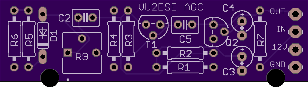
AGC kits
|
It has come to my attention after the fact that the AGC kits I sold a few weeks back do not match the schem with the parts placement. I am very sorry about the mix up, If memory serves you should still have all the right values to match the schem. Taking the 100k from the input and adding just after the .1uf cap after the 2n3904, use the 10k on the input. ?If anyone has any questions or needs parts please e-mail me directly, I will ship any parts missing or needed free of charge to help make up for the mistake. ?Again sorry about the mix up this was my 1st run of any type of kit and have learned a few lessons to say the least. dherron at live dot com ?N8DAH |
|
Joe Puma
toggle quoted message
Show quoted text
On Feb 8, 2018, at 2:57 PM, N8DAH <Dherron@...> wrote:
|
开云体育Do you have a list of the components by designation Ex: R1, R2, C1, C2.The pcb does not show values only designations. On 2/8/2018 8:31 PM, N8DAH wrote:
|
开云体育read the link From: [email protected] <[email protected]> on behalf of Ed Kelley via Groups.Io <ekelley946@...>
Sent: Friday, February 9, 2018 4:15 PM To: [email protected] Subject: Re: [BITX20] AGC kits ?
Do you have a list of the components by designation Ex: R1, R2, C1, C2.
The pcb does not show values only designations. On 2/8/2018 8:31 PM, N8DAH wrote:
-- David ?N8DAH |
|
Joe Puma
开云体育
|
|
toggle quoted message
Show quoted text
|
|
Does anyone know what the typical output level of the first AF amp should be for a strong signal? I built the AGC amp shown in the message by Joe Puma and the AF output begins to distort with an input of 300mv to 350mv RMS. I haven't yet built a spreadsheet to see how much AGC action is provided as the AF level goes up. Maybe I can get to that tomorrow. I don't have any way to sweep the amplitude of the input AF, only the frequency. So I'll have to build everything up manually a point at a time in order to see what compression is provided.?
|
|
Joe Puma
toggle quoted message
Show quoted text
On Feb 10, 2018, at 3:15 PM, ekelley <ekelley828@...> wrote:
|
开云体育Tim, please have a look on my folder (DK5LV) subfolder "LTSPICE
XVII" in the BITX 20 group. I have made simulations of the AF
preamp, the gain ist 46 dB.? I can confirm that the LTSPICE
simulations comply with measurements I made using my BITX40. In the subfolder "BITX40 level diagramme" You can find my level
diagramme. I can confirm that my assumptions on the gain of the
stages in the BITX 40 comply with the measurements of my BITX 40.
This means that the AF preamp is momentarily the stage which
limits the distortion free dynamic range of the complete BITX40.
The high gain of the audio string is necessary to get a suitable
overlal audio power. To put an AGC system between the output of
the AF preamp and the LM386 does not improve the ability of the
BITX 40 for? a maximum distortionless RF antenna input signal.? DK5LV Am 10.02.2018 um 22:18 schrieb Tim
Gorman:
Does anyone know what the typical output level of the first AF amp should be for a strong signal? I built the AGC amp shown in the message by Joe Puma and the AF output begins to distort with an input of 300mv to 350mv RMS. I haven't yet built a spreadsheet to see how much AGC action is provided as the AF level goes up. Maybe I can get to that tomorrow. I don't have any way to sweep the amplitude of the input AF, only the frequency. So I'll have to build everything up manually a point at a time in order to see what compression is provided.? |
|
Henning,
Thank you for the information. Your data is quite informative. I have bookmarked your link. I don't have an actual radio to test against. I am hoping my ubitx will ship in the next few days.? In measuring the agc board itself, using a 1K resistor as a load, a 100mvPP input results in an 18mvPP output across the 1K resistor. Since I don't know the load resistance of the volume pot and the final AF amp I just picked 1Kohm as a representative value. If this is true the volume will have to be turned up significantly in order to get the same speaker output. The AGC board seems to provide a gain of 5 (18mv to 90mv) while the gain of the input is about 12 (100mvPP to 1200mvPP) so it does seem to provide significant gain compression as the output of the AF preamp goes up.? I look forward to actually measuring the AGC boards functionality when I get my ubitx put together.? tim ab0wr |
开云体育Tim, the AF potentiometer deliverd by HF Signals with the BITX40 kit
has a value of 10k. Am 11.02.2018 um 15:39 schrieb Tim
Gorman:
Henning, |
|
Joe Puma
开云体育Okay I spent some time trying to understand the change. You sent 10k (103) resistor tapped to the paper. ?Replace that with the 100k (1000) near the input and that’s it right. Okay I will make the change soonThanks, Joe KD2NFC? On Feb 8, 2018, at 9:31 PM, N8DAH <Dherron@...> wrote:
|